Engineering and Applied Science Letter
ISSN: 2617-9709 (Online) 2617-9695 (Print)
DOI: 10.30538/psrp-easl2019.0030
The analysis of failure and reliability factors of impressed current cathodic protection (ICCP) design toward underwater line of warship (Case study in kri kcr-40 type)
Nengah Putra\(^1\), Romie Oktovianus Bura, Sovian Aritonang, Djoko Navalino, Joni Widjayanto
Indonesia Defense University Sentul, Sukahati, Citeureup, Bogor, West Java 16810, Indonesia.; (N.P & R.O.B & S.A & D.N & J.W)
Abstract
Keywords:
1. Introduction
There is a common problem in the readiness of the Main Defense Equipment of Weapon System (Alutsista) of Navy Indonesia Armed Forces which is often faced with one of them, it is Corrosion. Corrosion on KRI occurs in underwater ship buildings which are exposed to sea water conditions. Corrosion at the bottom of a ship's water line can result in personnel and material safety risks. There are 2 (two) ways to protect against corrosion, they are passive protection (by painting) and active protection (by cathodic protection method). In the KRI with KCR-40 type, the design of the bottom line of the ship's waterline protection has been carried out with ICCP, but the value of its failure risk and reliability is unknown, both functional and designs, so that the design of the tool cannot be used maximally.
This research aimed to determine the factors of failure and reliability value of the design-based ICCP (Reliability by Design) with the FTA and FMEA approach, the FTA aimed to identify the risks that contribute to the failure. This method was carried out with a top down approach, which began with the assumption of failure or loss from a top event then detailed the causes of a top event to a root cause, whereas FMEA was a tool used to analyze the reliability of a system and the causes of its failure, by providing basic information about the system reliability prediction, design, and process.
This research was expected to be used as a reference in planning the development of a forced current method protection system (ICCP). This research was limited to several aspects, it was testing the function of the ICCP in a static state, the analysis used was limited to failure factors and nonparametric reliability calculations. There were several previous researches as supporting research, namely FTA and FMEA models are used as a risk analysis method in safety system [1]. The paper presents about FMEA and Fishbone diagrams for possible failures that occur in the engine [2]. FTA and FMEA as a model for evaluating failures or important parts of the system [3]. FTA and FMEA as a model for analyzing the reliability of BPRS field connection configurations [4]. FTA and FMEA as a model to identify the potential impact of failures in the Requirements Phase [5].
HAZOP and FTA to provide risk analysis in the chemical industry [6]. FTA and FMEA as a model to improve quality in the cleaning process [7]. FTA and FMEA as a method for identifying critical function level failures in metal printing additive manufacturing systems [8]. FTA and FMEA as a method to improve the quality of large industrial products at the end consumer level [9]. FTA and FMEA as a method to identify modes, components, and sub-systems of critical failures in CNC systems [10]. FTA and FMEA as a method for analyzing failure modes and effects on power plant boilers.
The systematically of the paper is organized as follows. Section 2 presents the theory of Fault Tree Analysis (FTA), Failure Mode Effect Analysis (FMEA), Corrosion, Reliability, Flowchart of research. Section 3 and Section 4 explain the result and discussion of research. Section 5 describes conclusion of the research.
2. Material/Methods
2.1. Corrosion
Corrosion can generally be defined as a deterioration in the quality or destruction of a metal by reacting with its environment [11]. Reactions in this corrosion produce metal oxides, metal sulfides or other reaction products. Corrosion is divided into two according to the type of reaction, they are chemical corrosion or dry corrosion and electrochemical corrosion or wet corrosion [12]. Dry or chemical corrosion is a process of corrosion that occurs through pure chemical reactions without electrolytes, usually occurring at high temperatures without the presence of water vapor. Electrochemical corrosion or wet corrosion occurs when the reaction takes place in an electrolyte and there is a transfer of electrons between the materials concerned, this reaction is what happens a lot in the corrosion process [13]. Corrosion process also occurs due to the tendency of a metal to turn into a more stable state through an oxidation reaction, where the oxidation tendency of a metal varies depending on the reduction potential. Basically the process of corrosion is the dissolution of metals by the reaction of metal surfaces with chemicals contained in the metal environment. If the metal is exposed to seawater or freshwater medium which has a pH close to neutral then the metal will spontaneously oxidize according to the reaction [11]:- Anode;
- Cathode;
- Electrolytes;
- Metal Joints.
2.2. Impressed current cathodic protection (ICCP) method
In planning the cathodic protection system with the ICCP method on ships, there are some things that are absolutely considered so that planning can be carried out on target, it is minimizing the occurrence of corrosion on the surface of the protected ship, including [15]:
- The condition of the protected environmental structure;
- Operational environmental conditions;
- Equipment used.
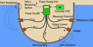
The purpose of this ICCP is to minimize the corrosion or corrosion that occurs in metals immersed in water. Corrosion protection in open hulls and hidden areas such as sea-chests are generally carried out at a certain level except when making special installation plans [16]. Protection of the hull by the ICCP method, which is a method of protection by providing electrons to the hull with the help of an external source of electric current. The electrons given to the material come from permanent anodes made of metal [17].
The basic principle of the ICCP system is to provide more negative potential, so that the metal will move into the immune zone. The difference between the corrosion zone and the immune zone is based solely on definition, but in reality even though the metal is in the immune zone, corrosion continues at a slower rate [18]. The more negative potential given will slow down the anodic reaction, conversely the cathodic reaction will be faster, as a result the metal will become more cathodic [19]. Hexagonal tiling under small cell complex is given in Figure 1.
Figure 1. Hexagonal tiling under small cell complex
2.3. Reliability and probability of underwater ship building
Mode of failure in underwater ship hull, among others, is the loss of service capability (loss of serviceability), loss of human function either partially or as a whole. The consequences of a failure vary greatly, including the decline in service life, increased maintenance costs, user costs, the impact on the environment and this will all be seen clearly that some consequences cannot be compared and cannot be evaluated in monetary terms [20]. In underwater hull, a vital failure criterion is the loss of structural strength which influences the reduction in underwater hull plate thickness [21]. The thickness reduction of the underwater ship hull one of which comes from corrosion. One of the influencing factors is the corrosion attack on the outside of the hull plate (external corrosion) which is in direct contact with the sea water environment.2.4. Fault tree analysis (FTA) method
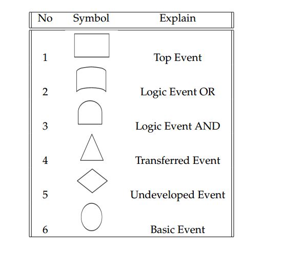
Fault Tree Analysis is an analytical tool that graphically translates combinations of errors that cause system failure. This technique is useful to describe and assess events in the system [22]. This Fault Tree Analysis method is effective in finding the core problem because it ensures that an undesirable event or loss caused does not originate at a single point of failure. Fault Tree Analysis identifies the relationship between causal factors and is displayed in the form of an error tree that involves a simple logic gate. There are 5 stages to carry out analysis with Fault Tree Analysis (FTA), which are as follows [23]:- Define the problem and boundary conditions of a system under review;
- A depiction of the Fault Tree graphic model;
- Finding the minimum cut set from the Fault Tree analysis;
- Perform a qualitative analysis of the Fault Tree;
- Perform a quantitative analysis of the Fault Tree.
Table 1. FTA Symbols
2.5. Failure mode effect analysis (FMEA) method
Failure Mode and Effect Analysis (FMEA) is a systematic approach that applies a labeling method to help the thought process used by engineers to identify potential failure modes and their effects [25]. FMEA is a technique of evaluating the reliability of a system to determine the effects of the failure of the system. Failures are classified according to the impact they have on the success of a system's mission. The purpose of FMEA is to take action to minimize failure, starting with the highest consequences. There are five types of FMEA that can be applied in a manufacturing industry, they are:- Systems, focusing on functions [26]. System globally;
- Design, focusing on product design;
- Process, focusing on the production and assembly processes;
- Service, focusing on service functions;
- Software, focusing on software functions.
- Frequency (occurrence).
In determining this occurrence can be determined how much disruption can cause a failure in maintenance operations and plant operations. - Severity.
In determining the level of damage (severity), it can be determined how serious the damage is resulting from the failure of the process in terms of maintenance operations and plant operations. - Detection rate.
In determining the level of detection it can be determined how the failure can be known before it occurs. The detection rate can also be influenced by the number of controls that govern the process netting. The more controls and procedures that govern the netting system for handling maintenance operations and plant operations, it is expected that the detection rate of failure can be even higher. - Risk Priority Number (RPN).
This value is a product of the results of the multiplication of severity, incidence, and detection rates. RPN determines the priority of failure. RPN has no value or meaning. This value is used to rank potential process failures. The RPN value can be shown by the following equation:
A protected structure
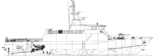
In designing this forced current cathodic protection system, the structure to be protected is the hull below the waterline KRI Terapang - 658. Following are the data on the KRI Terapang - 658 hull:- Materials: High Tension steel AH-36
- Length over all: 46.23 meter
- Length of water line: 41.4 meter
- Length between Perpendicular (Lbp): 40.8
- Length Perpendicular (Lpp): 40.8
- Length (B): 7.9
- Draft: 1.9
- High :4.25
- Coefisien blok (Cb): 0.39
Figure 2. Indonesian Warship KCR 40 Type
2.7. Goal
The steps of the FMEA method in this research are:- Determining the potential failure modes, causes of failure and the effects of failure, obtained from the results of discussions and interviews with the designer.
- Furthermore, the weighting of Severity, Occurrence and Detection is weighted for each failure mode, weighting is obtained from the results of discussions with the designer.
- After obtaining the results of Severity, Occurrence and Detection for each failure mode, the Risk Priority Number (RPN) can be calculated, so that the greatest risk of process failure is obtained. Based on the results of this high failure mode RPN, the FTA method is then used to see the root causes of the high failure mode. The steps of the FTA method in this research are:
- Building or creating a fault tree with the highest failure mode is used as the top event.
- Determining the minimum cut set of each basic event failure mode that is highest.
- After the results of the minimum cut set are known, then a qualitative FTA analysis and Quantitative FTA analysis are performed to determine the probability and reliability values of each basic event.
2.8. Flowchart
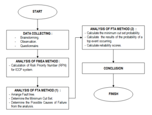
The flowchart of this research is given in Figure 3.Figure 3. Flowchart of Research Paper
3. Result
3.1. Severity determination
The severity of the effects caused by failure in each ICCP tool trial process (Table 2).Table 2. Result of Severity Score for Failure in ICCP.
| Parts | Failure Mode | Potential Failure Effect | S |
|---|---|---|---|
| Microcontroller | Error | ICCP tool does not work | 8 |
| Steel potential indicator and rectifier indicator |
Do not designate numbers correctly | Data displayed is inaccurate | 8 |
| Fan | Motor on fire | All Components in the box are at risk of damage | 7 |
| Transformer | Burnt out | ICCP tool does not work | 9 |
| Sensor Ag-Ag/Cl | Broken | Cannot provide data input of Corrosion protection limit |
2 |
3.2. Determination of Rating Detection
The level of occurrence of how often the effects of these failures appear in each ICCP tool trial process. The result of occurrence scores for failure in ICCP is given in Table 3.Table 3. Result of Occurrence scores for Failure in ICCP.
| Parts | Failure Mode | Potential Failure Effect | O |
|---|---|---|---|
| Microcontroller | Error | Main power source is in trouble (voltage fluctuates) | 1 |
| Steel potential indicator and rectifier indicator | Do not designate numbers correctly | 5 | |
| Fan | Motor on fire | 4 | |
| Transformer | Burnt out | 2 | |
| Sensor Ag-Ag/Cl | Broken | Impact, natural factors | 1 |
Table 4. Result of Detection scores for Failure in ICCP.
| Parts | Failure Mode | Potential Failure Effect | D |
|---|---|---|---|
| Microcontroller | Error | Main power source is in trouble (voltage fluctuates) | 1 |
| Steel potential indicator and rectifier indicator | Do not designate numbers correctly | 6 | |
| Fan | Motor on fire | 4 | |
| Transformer | Burnt out | 2 | |
| Sensor Ag-Ag/Cl | Broken | Impact, natural factors | 1 |
The highest component detection value is steel potential indicator and rectifier indicator with value of 6 with failure mode "not pointing to the correct number" and the cause of potential failure "temperature in the box is hot and voltage is up and down". A value of 6 indicates a detection rate of "Low" with the statement "Low the possibility of design controls will find a potential cause of mechanical damage or a cause of subsequent failure". Other component detection values include fans with a value of 4, Transformer with a value of 2, and the lowest value with a value of 1 it is the microcontroller and the Ag-Ag/Cl sensor.
3.3. Determination of risk priority number (RPN) value
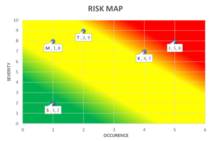
After determining the rating of Severity, Occurance, and Detection, the next step is to calculate the Risk Priority Number (RPN) value. Failure modes which later have the highest RPN values will be viewed using the Fault Tree Analysis method so that the root of the problem is known and corrective action can be taken. The result of risk priority number (RPN) scores for failure in ICCP is given in Table 5 and the risk map of risk priority number (RPN) for ICCP is given in Figure 4.Table 5. Result of Risk Priority Number (RPN) scores for Failure in ICCP.
| Part | Failure Mode | (S) | (O) | (D) | RPN = S*O*D |
|---|---|---|---|---|---|
| Microcontroller | Error | 8 | 1 | 1 | 8 |
| Steel potential indicator and rectifier indicator | Do not designate numbers correctly | 8 | 5 | 6 | 240 |
| Fan | Motor on fire | 7 | 4 | 4 | 112 |
| Transformer | Burnt out | 9 | 2 | 2 | 36 |
| Sensor Ag-Ag/Cl | Broken | 2 | 1 | 1 | 2 |
Figure 4. Risk Map of Risk Priority Number (RPN) for ICCP
- Steel potential indicator and rectifier indicator:
In this component the potential failure mode that occurs is "not pointing to the correct number" and the cause of the potential failure is "Temperature in the box is hot and the Voltage is Up and Down" then the actions that must be taken include: - Redesigning the laying of some components of the tool compilers to pay attention to the circulation of the freezing in the box, so that the tool works more optimally.
- Controlling is carried out periodically while the tool is operating.
- Ensuring that the electrical power used is stable so that there are no problems with the ICCP device during the ICCP device.
- Making sure to use a fan with a good quality motor winding.
- Having control Periodically and scheduled while the tool is operating.
- Transformer.
In this component, the potential failure mode that occurs is "burning" and the cause of the potential failure is "The quality of the wire coil and transformer core is poor and the temperature in the box is hot", so actions that should be taken to reduce the risk value include:- Using a transformer that is coiled and the core of the transformer is in good quality in accordance with the requirements of the tool specifications.
- Making sure the cooling fans are always in good condition if you need to install a backup fan with a parallel system automatically so that the temperature in the box is maintained.
- Microcontroller.
In this component the potential failure mode that occurs is "error" and the cause of the potential failure is "Main power source is in trouble (voltage is up and down)", then the actions that should be taken to minimize the value of risk include: Implementing controls on the main electric power source scheduled to ensure a stable supply of electricity.
Analysis of FTA
After the results of calculations with the FMEA method are known to be the highest RPN value of each failure mode, then the next step will look for the root causes of the failure mode in order to find the next stage of improvement recommendations. In determining the root of the problem, the Fault Tree Analysis (FTA) method is used.
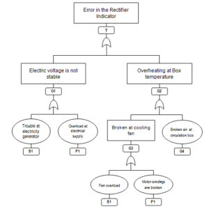
From the previous step in the FMEA method obtained two failure modes that have high RPN values, it is in the "Steel potential indicator and rectifier indicator" section and the "Fan" component with failure mode in the steel potential indicator and rectifier indicator "cannot show the correct number" while on the fan with the fan motor failure mode on fire. Then the next step is to define the top event component that has a high RPN value by creating an error tree/FTA. The influence of the auxiliary parameter on the local velocity distribution with the property \(Η=0.2\) is given in Figure 5.
Figure 5. Influence of the auxiliary parameter on the local velocity distribution with the property \(Η=0.2\)
- Qualitative Analysis of FTA.
Qualitative analysis is to get a combination of failures that cause the top event in a system or the minimum cut set itself. The results of a qualitative analysis of the failure modes above occur if the following events occur. These events are:- P1: There is an overload on the electricity provider.
- P2: Overloaded cooling fan.
- P3: Bad quality of fan motor.
- P4: The circulation design in the box is not good.
- Quantitative Analysis of FTA.
From the results of this analysis, the probability of occurrence of each basic event can be searched with data of some damage as much as 7 events during the ICCP tool experiment, so that the probability of each event is (Table 6):Table 6. Result of Risk Priority Number (RPN) scores for Failure in ICCP.
No Classification of
Basic eventEffect Probability (pf) 1 Overload occurred at the electricityprovider Steel potential indicator and rectifier
indicator are broken0.28 Weak fan motor 2 Steel potential indicator and rectifier
indicator are brokenSteel potential indicator and rectifier
indicator are broken0.28 The temperature in the box
is hot so that other components are disrupted3 Bad quality of fan motor Fan work is not optimal 0.42 Hot box temperature Fan is burning 4. Circulation design in the box is not
goodSteel potential indicator and rectifier
indicator are broken0.14
Discussion
From the ICCP tool test results showed that there were several problems at the initial stage of the trial, with a total of 7 problems, then using the FMEA method to identify the problem, from the initial identification conducted there were 5 components to be assessed and calculated the risk value. The 5 components included: Microcontroller, Voltage and Ampere Indicator, Fan, Transformer, and Ag-Ag/Cl Sensor.
The next FMEA step is determining the rating/weighting of Severity, occurrence, and Detection failure mode, determining the rating/weighting is through an interview with the tool designer. From the results of data processing the determination of SOD rating obtained RPN results with the highest value, it is the component of "steel potential indicator and rectifier indicator" and the "fan" component. Furthermore, based on the value (Occurrence) and severity of the effect (Severity) that has been weighted, it is necessary to know the risks that must be minimized by using the Risk Map matrix, from risk mapping components that have the highest value/are in the red zone carried out several mitigations. After mitigating the components in the red zone, data processing is continued using the FTA method.
In the FTA method the two components that have a high value are mapped to a failure tree to find out the basic event of the problem. Data processing by the FTA method is done qualitatively and quantitatively, if the data qualitatively produce a minimum cut set of the top events of the two components that have high RPN values. From the results of FMEA and FTA analyzes that have been obtained, the results of data processing according to the purpose of this research were known to be "factors causing failure and reliability of the design of ICCP tool designs" and "mitigation of the tool compiler components that have a high level of risk".
5. Conclusion
Based on the results of the research that has been carried out, it can be concluded that:- The main factors causing failure in the design of ICCP tools occur in the component of "Steel potential indicator and rectifier indicator" with a failure mode "not pointing to the correct number", this will result in corrosion control which is expected to be uncontrolled properly and correctly due to incorrect data input. After analyzing the FTA, the reliability value was 33\%.
- Mitigation of tool components that have a high level of risk among other things in the "Indicator of steel potential and rectifier indicators": the first was to redesign the laying of some components of the tool compilers to pay attention to the circulating circulation in the box so that the tool works more optimally, the second was to carry out periodic control while the device was operating, and third was to ensure that the electrical power used was stable so there were no problems with the ICCP device while the ICCP device was operating.
Acknowledgements
This study was supported by Studies Program of Defense Technology in Indonesia Defense University. We thank you to the 2nd Fleet Command in Surabaya, East Java for this research data. We also thank you to Kukuh Susilo, M. Eng. for smart discussion in corrosion field.Competing Interests
The authors declare no competing interest.References
- Shafiee, M., Enjema, E., & Kolios, A. (2019). An integrated FTA-FMEA model for risk analysis of engineering systems: a case study of subsea blowout preventers. Applied Sciences, 9, 1-15. [Google Scholor]
- El-Dogdog, T. M., El-Assal, A. M., Abdel-Aziz, I. H., & El-Betar, A. A. (2016). Implementation of FMECA and fishbone techniques in reliability centred maintenance planning. International Journal of Innovative Research in Science, Engineering and Technology, 5(11), 18801-18811. [Google Scholor]
- Shrivastava, R., & Singh, A. (2018). Research on Failure mode and effect analysis of Diesel Engine. International Research Journal of Engineering and Technology, 5(5), 3516-3521. [Google Scholor]
- Jenab, K., & Moslehpour, S. (2016). Failure analysis: case study challenger SRB field joint. International Journal of Engineering and Technology, 8(6), 401-404.[Google Scholor]
- Pareek, P. K., & Nandakumar, A. (2015). Failure mode effective analysis for requirement phase in small software firm. International Journal of Advanced Technology in Engineering and Science, 3(2), 188-194. [Google Scholor]
- Fuentes-Bargues, J., González-Cruz, M., González-Gaya, C., & Baixauli-Pérez, M. (2017). Risk analysis of a fuel storage terminal using HAZOP and FTA. International Journal of Environment Research and Public Health , 14(705), 1-26. [Google Scholor]
- Fragassa, C., & Ippoliti, M. (2016). Failure mode effect and criticality analysis (FMECA) as a quality tool to plan improvements in ultrasonic mould cleaning systems. International Journal for Quality Research, 10(4), 847-870. [Google Scholor]
- Peetersa, J., Basten, R., & Tinga, T. (2018). Improving failure analysis efficiency by combining FTA and FMEA in a recursive manner. Reliability Engineering and System Safety, 172, 36-44. [Google Scholor]
- Fragassa, C., Pavlovic, A., & Massimo, S. (2014). Using a total quality strategy in a new practical approach for improving the product reliability in automotive industry. International Journal for Quality Research, 8(3), 297-310 [Google Scholor]
- Patil, R. B., & Kothavale, B. S. (2018). Failure modes and effects analysis (FMEA) of computerized numerical control (CNC) turning center. International Review of Mechanical Engineering , 12(1), 78-87.[Google Scholor]
- Roberge, P. R. (1999). Handbook of Corrosion Engineering. HIghstown, United State : Mc Graw Hill Company [Google Scholor]
- Fontana, M. G. (1987). Corrosion Engineering. Singapore: McGraw Hill,Inc. [Google Scholor]
- Peabody, A. (2001). Control of Pipeline Corrosion. Houston: NACE International. [Google Scholor]
- NACE, I. (2002). NACE Corrosion Engineer's Reference Book. Houston: NACE International The Corrosion Society [Google Scholor]
- Balla, E. E., & Rahmat, M. F. (2013). System identification modelling and IMC basic control of impressed current cathodic protection systems. International Journal On Smart Sensing And Intelligent Systems, 6(5), 2055-2074. [Google Scholor]
- Bhuiyan, S. (2015). Effectiveness of Impressed Current Cathodic Protection System in Concrete Following Current Interruption. Singapore: RMIT University. [Google Scholor]
- Broomfield, J. P. (2004). The application of impressed current cathodic protection to historic listed reinforced concrete and steel framed structures. The Journal of Corrosion Science and Enginerring, 9, paper 15. [Google Scholor]
- Nguyen, C. V., Lambert, P., Mangat, P., O'Flaherty, F., & Jones, G. (2012). The performance of carbon fibre composites as ICCP anodes for reinforced concrete structures. ISRN Corrosion, 2012, Article ID 814923, 9 pages. [Google Scholor]
- Hogan, V. G., Lucas, K. E., & Wimmer, S. A. (2005). Shipboard impressed current cathodic protection system (ICCP) analysis. WIT Transactions on State of the Art in Science and Engineering, 7. [Google Scholor]
- Lounis, Z. (2006). Risk-based maintenance optimization of aging highway bridge decks. In Advances in Engineering Structures, Mechanics & Construction (pp. 723-734). Springer, Dordrecht.[Google Scholor]
- Price, S. J., & Figueira, R. B. (2017). Corrosion protection systems and fatigue corrosion in offshore wind structures: current status and future perspectives. Coatings, 7(25), 1-51.[Google Scholor]
- Foster, S. T. (2004). Managing Quality : an Integrative Approach (2nd ed.). New Jersey: Prentice Hall [Google Scholor]
- Upadhya, M. S. (2012). Fuzzy fault tree analysis - A case study. Journal of Computer Applications, V(2), 60-63[Google Scholor]
- Baig, A. A., & Ruzli, R. (2014). Estimation of failure probability using fault tree analysis and fuzzy logic for CO2 transmission. International Journal of Environmental Science and Development, 5(1), 26-30. [Google Scholor]
- Thakore, R., Dave, R., & Parsana, T. (2015). A case study: A process FMEA tool to enhance quality and efficiency of bearing manufacturing industry. Scholars Journal of Engineering and Technology , 3(4B), 413-418.[Google Scholor]
- Shaghaghia, M., & Rezaie, K. (2012). Failure mode and effects analysis using generalized mixture operators. Journal of Optimization in Industrial Engineering , 11, 1-10 [Google Scholor]

