
As we are aware with the limitation of human eyes, for the observation of tiny particles and for the observation of distant objects we require some instruments. For the observation of tiny invisible materials, we use microscopes and for the observation of distant objects beyond the perception of human eyes use telescope. Today microscopic techniques become an integral part in the analysis of biomaterials and nanomaterials. With the help of advanced microscopic techniques like scanning electron microscope and transmission electron microscope the morphology of invisible small particles can be studied. Atomic Force Microscopy can provide images of the surface of biomaterials with nanoscale resolution and probe mechanical properties at molecular scale. Fluorescence microscopy facilitates the visualization of bio-molecular interactions and cellular processes, while confocal microscopy provides optical sectioning capabilities for three-dimensional imaging [1– 4].
Eyes of animal are optical instrument. Here the photons are translated into electrical signals and the animal can recognize light and color. Under the condition of normal day light or brightness the resolution of the naked eye is around 1 arc minutes that is equal to 1/60 degrees or 0.003 radians. If one is desirous to visualize objects smaller than this, some external aid is required. Microscope is the instrument used for magnification and resolution of the smaller objects. A significant contribution in the area of microscopy is devoted by Dutch Physicist Antonie Philips van Leeuwenhoek. Later on much advancement has taken place in the area of microscopes.
These are main optical components that refract, or bend, light rays as they pass through, resulting in the formation of images. They are made up of transparent materials such as glass or plastic and have curved surfaces that cause light rays to converge or diverge. Lenses play a crucial role in various optical instruments, including cameras, telescopes, microscopes, eyeglasses, and projectors. The properties of the lenses depend upon their focal length, aperture and aberration. Therefore, it is essential to select and design proper lenses as per our goal. [5– 7]:
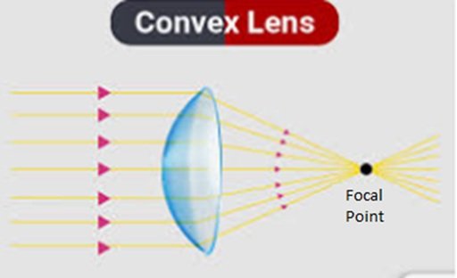
Convex lenses are also known as converging lenses and shown in Figure 1, are optical components with curved surfaces that bulge outward. They are thicker at the center and thinner at the edges, causing light rays passing through them to converge or focus at a point.
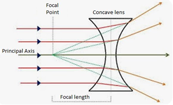
Concave lenses are also known as diverging lenses and shown in Figure 2, are optical components with curved surfaces that curve inward. They are thinner at the center and thicker at the edges, causing light rays passing through them to diverge or spread out.
The main properties of microscopy such as Resolving power, and magnifying power which depends upon several factors such as Objective Numerical Aperture, Operating wavelength, etc. and these are described in the following section.
This is also called as resolution. This is the fundamental and very important property of any microscopic technique which can distinguish between two closely placed objects at distinct entities. In other words, it measures the system’s ability to reveal fine details in a specimen and resolve them as separate entities rather than blending them together into a single image. The resolving power of any instrument depends upon several factors such as numerical aperture (NA) of objective lenses, the wavelength of the light used for illumination and quality of the optical components [8, 9]:
It is a measure of the ability of an objective lens to gather light and resolve finer details in a specimen. A higher NA corresponds to a larger cone of light entering the lens, which improves the ability of the lens to resolve fine details. As a result, objective lenses with higher numerical apertures typically have better resolving power. It is given as below, \[NA=nsin\theta. \tag{1}\]
In the above equation n indicates the refractive index and \(\theta\) is the one-half of the angular aperture A. It is worth to mention here that the resolving power of the material does not merely depend upon refractive index and numerical aperture. There are other important factors also such as type of specimen, coherence of illumination, degree of aberration correction and other factors such as contrast enhancing methodology either in optical system of the microscope or in specimen itself.
As discussed in the above paragraph the one of the other factors which can influence the resolving power of microscope is the wavelength of light. According to Abbe’s diffraction limit, the minimum resolvable distance (d) between two points in a specimen is approximately half the wavelength of light (\(\lambda\)) divided by the numerical aperture of the objective lens (NA). Therefore, shorter wavelengths of light can provide better resolution than longer wavelengths.
The quality of optical components—including lenses, mirrors, and prisms—is pivotal in determining the resolving power of a microscope. Any imperfections, such as surface irregularities or optical aberrations, can significantly degrade image quality and diminish resolving power. To achieve optimal resolution, high-quality lenses with minimal chromatic and spherical aberrations are essential. Precision in the design, manufacturing, and alignment of optical elements ensures that light paths remain accurate, minimizing distortion and maximizing clarity. This level of craftsmanship is critical in modern microscopy, where even minute imperfections can affect the observation of fine details.
While magnification is not directly related to resolving power, it can influence the perceived clarity and detail of an image. Higher magnification levels can make fine details more apparent, but they do not necessarily improve resolving power if the optical system cannot distinguish between closely spaced objects. Thus, resolving power is a key parameter that determines the ability of a microscope to reveal fine details in a specimen. By optimizing factors such as numerical aperture, wavelength of light, and optical quality, microscopes can achieve higher resolving power and produce sharper, more detailed images of microscopic structures.
As the word indicates, magnifying power of the microscope is its ability to enlarge the size so that the specimen become visible to human eyes. The magnifying power is commonly expressed as the numerical value indicating the degree to which the specimen appears larger compared to the naked eye. The magnifying power of a microscope depends upon the objective lens as well as the eyepiece (ocular).
In compound microscope there are two lens one is known as objective lens and another is known as eye piece lens. The objective lens with various magnifying power is available which typically ranges from 4x to 100x or higher. The magnifying power of the objective lens is marked and specified on it such as 4x (low power), 10x (medium power), 40x (high power), or 100x (oil immersion). The lens can be rotated and magnification can be adjusted accordingly. When changing objective lenses, the magnification of the microscope changes accordingly.
The second type of lens required in compound microscope is the ocular or eyepiece lens. The further magnification of the image takes place with the help of ocular lens. Eyepieces commonly have magnification values ranging from 5x to 20x or higher.
We are interested in overall magnification resultant of magnification by eye piece and objective lens. The overall magnification as a result of magnification by both types of lens can be obtained by multiplying the magnification by objective lens and eye piece lens. For instance, the total magnification would be 10x * 10x = 100x if the objective lens and eyepiece each had a 10x magnification. Microscopes with multiple objective lenses and interchangeable eyepieces offer a range of magnification options to suit different applications and specimen sizes.
It is very clear that increasing magnification can exhibit smaller details of the objects. But it should be remembered that, magnification merely is not enough condition for better image resolution and quality. There are various factors which are equally responsible for better image quality such as numerical aperture, resolution, and optical aberrations. These factors play a crucial role in determining the clarity and detail of the observed image. Apart from this, the higher magnification levels may require additional techniques such as oil immersion or specialized imaging modes to maintain image quality and clarity. The various types of microscopes can be classified as below.
This type of microscope is the earliest version of microscope and supposed to be developed during 17th century in European countries. In optical microscope simple one or two lenses are used for magnification. The microscope can magnify the image of the within the focal plane. This type of microscope is having two fundamental parts known as eye piece (ocular lens) and objective (resolve or resolving noise) which is used for the magnification of image. The other import components of microscope are focus knob, light source, condenser etc. The optical microscope, also referred to as a light microscope, creates enlarged images of objects using a system of lenses and visible light. There are different types of optical microscopes such as phase contrast, confocal, stereo, compound, digital, inverted, stereo, stereo, and comparison microscopes.
Thus, we notice that optical microscope uses visible light and various optical components such as eye piece, objective lens, diaphragm, mirrors etc. which are jointly used to magnify small objects for detailed observation and analysis. By controlling the illumination, magnification, and contrast, optical microscopes furnish valuable insights into the scientific research, education, and industrial applications [10– 14].
As we are aware optical microscopes are of various types such as simple microscope and compound microscope. As the name indicates, simple microscope is the simplest type of microscope. This type of microscope is used to magnify the small objects which are otherwise invisible to human eyes. The simple microscope is made up of just one convex lens.
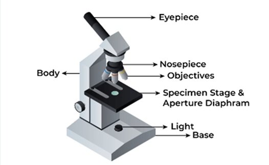
The concept of magnification using lenses dates back to ancient times, but it was during the 17th century that significant advancements in optics paved the way for the development of simple microscopes as shown in Figure 3. Dutch scientist Antonie van Leeuwenhoek is credited with the creation of some of the earliest and most powerful simple microscopes. Using meticulously crafted lenses, Leeuwenhoek was able to observe microorganisms and other tiny structures that were previously unknown to scientific community. As the name signifies simple microscope contains just a single convex lens mounted on a stand. The sample to be observed is placed on a flat surface beneath the lens, and the observer positions their eye close to the lens in order to view the magnified image. By adjusting the distance between the lens and the specimen, as well as the distance between the lens and the observer’s eye, different levels of magnification can be achieved.
Although simple microscope was invented earlier for the magnification of the object, it has several limitations. Some of the limitations encountered as listed as below:
Limited Magnification: We are well aware that the magnification depends upon power of the lens. We have discussed that if the microscope is made up of two types of lens, then the resultant total magnification is the product of magnification made by each type of lens. In simple microscope there is a single convex lens. Hence, there is much limitation in the magnification. Thus, simple microscope has lower magnification as compared with compound microscope and other advanced microscope such as electron microscope and probe microscope.
Limited Resolution: Resolution is another important factor in microscopy. The simple microscope has poor resolution i.e. the two components cannot be properly distinguished from one another.
Aberrations: Aberration is the phenomenon of deviation of light rays through lens, causing image to be blurred. In an ideal system, every point on an object will focus toa point of zero size on the image. The single lens simple microscope is more susceptible to aberrations. There are various types of aberrations such as chromatic aberration, distortion, spherical aberration etc. The image is distorted and its quality is adversely affected due to such types of aberrations.
Depth of Field: Simple microscope is a type of optical microscope which uses visible light for radiations. Thus, it has shallow depth of fields, which indicates that only thn section of the specimen is in focus at a time. This can make it challenging to observe three-dimensional objects or specimens with uneven surfaces.
Limited Versatility: Simple microscopes are generally less versatile than compound microscopes in terms of their ability to accommodate different specimen types and observation techniques. Compound microscopes offer a wider range of magnifications, contrast methods, and imaging modes, making them more suitable for diverse applications.
No Köhler Illumination: This is the method of specimen illumination used for transmitted and reflected light in optical microscope. Here the primary limitation of critical illusion lies in the formation of image. Kohler illumination addresses this by ensuring the image of the light source. Simple microscopes lack this illumination technique, which can result in uneven lighting and glare, affecting image quality.
Limited Field of View: The field of view of a simple microscope is often smaller compared to compound microscopes. This can restrict the size of specimens that can be observed and may require more frequent movement of the specimen or lens to view the entire sample [15– 17].
A compound microscope is a sophisticated optical instrument used to magnify small objects with high resolution. Unlike simple microscopes, which consist of just one lens, compound microscopes utilize multiple lenses and complex optical systems to achieve higher magnification and clarity. In the 19th century, several notable scientists and inventors contributed to the refinement and development of compound microscope designs. Friedrich Wilhelm Schiek of Germany introduced achromatic lenses in the early 19th century, which significantly reduced chromatic aberration and improved image quality. Joseph Jackson Lister of England developed the achromatic lens in the 1830s, further enhancing the optical performance of compound microscopes. In the 20th and 21st centuries, compound microscopes underwent further modernization and technological advancements. Innovations such as the introduction of binocular observation, fluorescence microscopy, phase contrast microscopy, confocal microscopy, and digital imaging have expanded the capabilities of compound microscopes and enabled new avenues of scientific exploration.
Compound microscope is a type of optical microscope. The compound microscope is equipped with eye piece and objective lens. The total magnification produced by compound microscope is the resultant multiplication of the magnification produced by eye piece and objective lens. The compound microscope is provided with diaphragm and mirror. This type of microscope is widely used for the study of biological samples in laboratories.
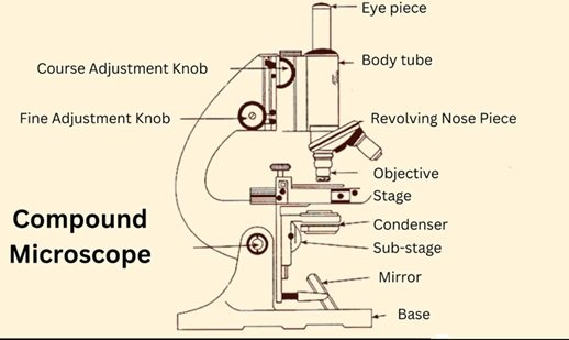
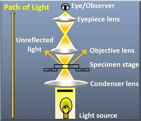
The modern advanced compound microscope is shown below in Figure 4. The working principle of compound microscope is based upon optical magnification and resolution. The mirror is placed at the bottom of microscope. This mirror can be rotated in different directions. When light passes through the objective lens and interacts with specimen. This undergoes refraction and forms the magnified image [18– 20]. The lens is of three types viz. simple lens or magnifying lens, compound lens and oil immersion lens.
Objective Lenses: The compound microscopes are equipped with objective lens. There are different types of objective lens based upon magnification. The commonly used objective lens are 4x, 10x, 40x and 100x. The number indicates the magnification produced by that particular lens. The objective lens is made up of convex lens. The length are having different focal length.
Eyepiece (Ocular Lens): The eyepiece is the part of microscope through which we look and get the magnified image of the specimen. The eye pieces are provided with the additional magnification system using convex lens.
Stage: It is a flat platform where the sample to be observed is placed. is mounted for observation. A mechanical stage is required for working at higher magnification. Stage clips are required when there is no mechanical stage.
Condenser: This is the part of optical microscope which is used for collection and focus of the light from the source of illumination onto the specimen under study. It is located under the stage often in conjugation with diaphragm. The diaphragm controls the amount of light reaching the specimen.
Illumination Source: This is the source of light for working of microscope. Some of the microscope uses low voltage hydrogen bulb as the source of light. Incandescent lamps are source of illumination for compound microscope. The incandescent lamps are relatively inexpensive. The illumination system of standard optical microscope is designed to transmit light through the translucent object for viewing. In modern optical microscope a light source such as an electrical lamp or light emitting diode are used. Proper illumination is essential for obtaining clear and detailed images.
Coarse and Fine Focus Adjustments: There are two types of adjustment in microscope known as coarse adjustment and fine adjustment systems. The coarse adjustment knob quickly brings image into focus. The fine adjustment knob helps to maintain focus as magnification increases. The fine adjustment of microscope refines the focus of object under observation.
Cost: Although optical microscope is comparatively simple and cost effective. But compound microscope is costlier than simple microscope. The high quality research grade models with advanced features such as motorized stages, fluorescence capabilities, and digital imaging.
Complexity: The compound microscope is a type of optical microscope and it is comparatively complex as compared with simple microscope. Compound microscope is equipped with two lens i.e. eye piece and objective lens. In compound microscope diaphragm, condenser and other parts are located. Operating and maintaining a compound microscope requires a certain level of expertise, including skills in sample preparation, focusing, and adjusting illumination.
Limited Depth of Field: Compound microscopes have limited depth of fields. This means only a thin section of specimen is in focus at any given time. Thus, it is a challenge to observe three dimensional structure or specimens with uneven surfaces, as parts of the specimen may appear blurred.
Limited Working Distance: The working distance, or the distance between the objective lens and the specimen, is often limited in compound microscopes, especially at higher magnifications. This can restrict the types of samples that can be observed, particularly those that are thick or irregularly shaped.
Sample Preparation Requirements: Compound microscopes often require specimens to be prepared as thin sections or mounted on slides for observation. This may involve staining, fixing, or embedding the sample, which can introduce artifacts or alter the native properties of the specimen.
Light Sensitivity: Compound microscopes rely on transmitted or reflected light for illumination, which can be sensitive to variations in lighting conditions and sample transparency. Specimens with low contrast or weakly absorbing features may be difficult to visualize effectively under bright field illumination.
Resolution Limitations: While compound microscopes offer high magnification, their resolution is limited by the wavelength of light used for illumination and the numerical aperture of the objective lens.
A digital microscope is basically traditional optical microscope which is equipped with modern digital technology. Today we are living in modern world where everywhere digitalization has taken place. The benefits of digitalization is also taken by the optical instruments like microscope and new type of microscope developed known as digital microscope which is equipped with computer or tablet or some other sort of electronic instruments. [21– 27].
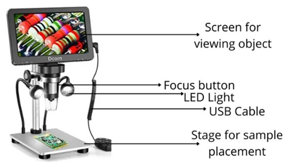
The digital microscope is an advanced version of microscope. This microscope is diagrammatically shown below in Figure 5. Digital microscope has several components such as digital imaging sensors such as charge coupled devices (CCD), metal oxide semiconductors (CMOS) sensors to capture and digitize image of specimen. The core of digital microscope is digital imaging sensors, which is typically CCD or CMOS sensors. Such sensors are capable of converting electromagnetic radiations in the form of light into electronic signals. These electronic signals can be processed through signal processing and digitalized by the microscope’s electronics. Instead of directly observing the specimen through eyepieces, users view the magnified images on a screen in real-time, allowing for easy sharing, analysis, and documentation.
Since the invention of microscope, there is continuous development in the technique. The modern digital microscope represents a significant improvement in the earlier technology. In the digital microscopy there is combination of optical microscopy and digital imaging capabilities which facilitates image capture, analysis and also documentation. If we trace the origin in the concept of digital microscopy we observe its origin may be traced in the development of digital imaging technique which was started in the mid of 20th century. In the budding stage of the digital microscopy, analog circuit camera is used and video recording devices were also used so as to capture the images of specimen. The images were viewed through optical microscope. Then the invention and development of CCD sensors made a drastic change and revolutionized digital imaging technology. CCD sensors offered higher sensitivity, improved signal-to-noise ratio, and faster image capture rates compared to previous analog imaging devices. These advancements paved the way for the integration of digital cameras into optical microscopes.
The instrumentation of modern Digital Microscope is depicted as below:
Digital Camera: As the name signifies, the digital microscope is provided with an in built digital camera. In certain cases, where in built digital camera is not available, an external camera may be attached so as to capture the images. The inbuilt or external camera may use various types of sensors such as CCD or CMOS sensors which can efficiently convert electromagnetic radiations in the form of light into digital signals.
Optical System: As studied in case of compound microscope, the digital microscope also has optical systems. The optical system comprising of objective lens, eye piece and other optical components. The lens is responsible for the magnification of the specimen. The lens in the eye piece provides additional magnification. Then the magnified image is captured and reaches to the camera.
Illumination Source: As we are aware that digital microscope is a type of optical microscope. All the optical microscope requires suitable illumination source. In case of digital microscope, the commonly used illumination sources are LED light or halogen bulbs which can illuminate the specimen.
Focus Adjustments: The structure of digital microscope is more or less similar to other optical microscopes. As in case of optical microscope, the digital microscope too contains systems for focus adjustments. There are two types of focus adjustment i.e. coarse focus adjustment and fine focus adjustment. These arrangements for adjustment may be manually operated or monitored, allowing the precise focusing.
Display Screen: The electromagnetic radiation in the form of light strikes and images are captured by digital camera. These are displayed in real time on a connected monitor, computer screen, or handheld device. Some digital microscopes feature built-in LCD screens for standalone operation without the need for external devices.
Digital microscopes offer several advantages over traditional optical microscopes:
Real-time Imaging: Real time imaging refers to the continuous monitoring of the biological process as they occur. This is a dynamic process they occur without relying on any repletion or synchronization. Users can view magnified images of specimens in real-time on a screen, eliminating the need to peer through eyepieces. This makes it easier to share observations with others and collaborate on projects.
Image Capture and Recording: As we have seen digital microscope is the advanced microscopic technique. Here high quality images and videos are captured and it becomes essential tools in various area of investigations such as biology, medicine, material science and even quality control. The digital microscope can capture and format images. Also the video can be captured and formatted. The digital microscope often requires various types of software required for resolution and image capture and processing. The digital microscope can be used in education, research, quality control and medical diagnosis.
Digital Measurement and Analysis: Digital measurement and analysis involve using digital tools and techniques to measure and analyze various parameters such as area, height, length and volume etc. Various digital microscopes are equipped with suitable software. This facilitates quantitative analysis and research.
Remote Viewing and Collaboration: Digital microscopes are many times facilitated with web based platform, remote desk sharing, virtual microscopy, augmented reality etc. The application of remote viewing lies in research activity, remote training and education, tele pathology, quality control and assurance etc.
Enhanced Imaging Features: Some digital microscopes are equipped with advanced technology for imaging such as image stitching, focus stacking, image enhancement which can improve the quality and clarity of magnification.
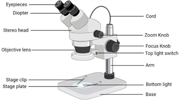
Stereo microscope, is an type of optical microscope. This microscope is also known as dissecting microscope. As the name indicates stereomicroscope can produce 3D image of the object. The ordinary microscope normally views the surface of the material whereas the inner portion remains un noticed. But the stereomicroscope can be used to analyze the deeper portion of the material. Thus, whenever if someone is interest to observe the inner portion of the object, the use of stereomicroscope is recommended. The stereomicroscope provides 3D image of the specimen under study. The initial version of stereomicroscope was essentially binocular, with two separate eye piece and objective lens mounted at a fixed distance from one another. In the modern day the stereomicroscope is available in various configurations, magnification levels and variable features. The advanced stereomicroscope is equipped with zoom capabilities, integrated lighting systems, ergonomic designs, digital imaging options, and advanced optics for enhanced image quality and performance [28– 32].
Binocular Vision: Binocular vision can be defined as the ability to perceive the world in three dimensions using both eyes. This is the fundamental aspect of human vision that enable for 3D vision so as to judge the distances, depth and spatial relationship in between the objects. The components of binocular vision may be defined as stereopsis, binocular disparity, convergence. The working of the binocular vision can be explained as each eye sees a slightly different image of the same scene. Now the image captured by each of the eye is combined in the brain. Thus, formation of 3D image takes place inside the brain. Now the brain calculates depth perception based on the difference in images between two eyes. As a result of binocular vision we get 3D image and we get information about the depth. And the arrangement allows the observer to view the specimen with both eyes simultaneously, providing depth perception and a three-dimensional (3D) view.
Separate Optical Paths: The optical path refers to the route that light travels through an optical system such as microscope, telescope and camera. The quality of the image is determined by the optical path. Here the optical system is divided into two separate paths for each eyepiece. Each path has its own objective lens, which collects light from different angles and projects two slightly different images of the specimen onto the observer’s eyes. These slightly offset images create the illusion of depth, enabling the observer to perceive the 3D structure of the specimen.
Magnification: The magnification of the stereomicroscope is to a smaller extent as compared with the magnification of compound microscope. The magnification of stereomicroscope can be 5x to 100x. Although magnification is lower, but formation of 3D image possible. This is the beauty of stereomicroscope. Thus, stereomicroscope may not be suitable instrument for the observation of microorganism or nanomaterials.
Binocular Observation: Stereo microscopes are equipped with two eyepieces (binocular) to provide a stereoscopic view of the specimen. This dual-viewing setup allows observers to perceive depth and spatial relationships between different parts of the specimen, enhancing the 3D visualization experience.
Separate Optical Paths: Each eyepiece of a stereo microscope is associated with a separate optical path, typically created by a pair of objective lenses positioned at a fixed distance apart. This arrangement produces slightly different perspectives of the specimen, mimicking the natural binocular vision of human eyes.
Low Magnification Range: Stereo microscopes typically offer magnification ranges from 5x to 100x, although some models may go higher. The lower magnification range allows users to observe larger specimens, such as biological samples, rocks, electronic components, or mechanical parts, while maintaining depth perception.
Long Working Distance: Stereo microscopes feature a longer working distance—the distance between the objective lens and the specimen—compared to compound microscopes. This enables users to manipulate and work on the specimen with tools or instruments while observing it under the microscope.
Zoom Capability: Many stereo microscopes are equipped with zoom lenses that provide continuous magnification adjustment within a certain range. This allows users to zoom in and out on the specimen to examine details at different levels of magnification while maintaining stereoscopic vision.
Illumination Options: Stereo microscopes may include various illumination options, such as top illumination (incident light) and bottom illumination (transmitted light), as well as adjustable brightness controls. Adequate illumination is essential for enhancing contrast and visibility of the specimen.
Ergonomic Design: Stereo microscopes are often designed with ergonomic considerations in mind, featuring adjustable eyepieces, inter-pupillary distance adjustment, and comfortable viewing angles to reduce eye strain and fatigue during prolonged observation sessions [33– 40]. Figure 6 illustrates Stereo Microscope.
Biology and Life Sciences: Observation of living organisms, dissection of specimens, examination of plant structures, and forensic analysis.
Material Science: Inspection of surfaces, analysis of surface defects, quality control in manufacturing, and examination of electronic components.
Geology and Earth Sciences: Study of rocks, minerals, fossils, and geological specimens.
Entomology: Observation and identification of insects and other arthropods.
Jewelry and Gemology: Examination of gemstones, jewelry, and precious metals for quality assessment and authenticity verification.
This type of microscope provides stereoscopic images which is useful for dissection especially in tumor surgery.
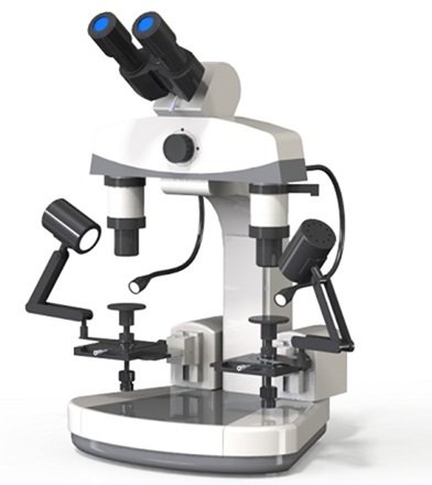
A particular kind of microscope called a comparison microscope enables the simultaneous observation and side-by-side comparison of two distinct specimens or objects. A synchronized view of the specimens is provided by the alignment of two distinct optical channels, each with its own set of objective lenses, eyepieces, and stages. Users can analyze the specimens’ similarities and differences in real time thanks to this innovative design.
Dual Viewing System: A comparison microscope typically has two eyepieces (binocular or monocular) and two separate optical paths, allowing two specimens or objects to be observed simultaneously.
Shared Stage: The microscope is equipped with a shared stage or platform on which both specimens can be placed for observation. The stage may have adjustable holders or clamps to securely position the specimens in alignment with each other.
Magnification Control: Comparison microscopes often have adjustable magnification settings for each optical path, allowing users to zoom in or out on the specimens independently. This flexibility in magnification enables detailed examination of specific features or areas of interest in both specimens.
Illumination System: Similar to other types of microscopes, comparison microscopes feature illumination systems to provide adequate lighting for the specimens. The illumination may be transmitted from below the stage (transmitted light) or directed from above (reflected light), depending on the type of specimens being observed.
Inter-pupillary Adjustment: Inter pupillary distance is the measurement of the distance in millimeter between the center of our two eyes. The optical industry this distance is used to properly align the center of eyeglass lenses with center of eyes. Many comparison microscopes offer inter-pupillary adjustment to accommodate users with different inter-pupillary distances. This feature ensures that both observers can comfortably view the specimens with proper alignment and eye relief.
Adjustable Bridge: Some comparison microscopes include an adjustable bridge or connecting arm that allows the distance between the two optical paths to be modified. This feature is useful for accommodating specimens of different sizes or shapes while maintaining alignment between the two views [41– 43]. The comparison Microscope is shown in Figure 7.
In forensic science: A comparison microscopes are used to analyze tool marks, firearms, cartridge cases, and bullets recovered from crime scenes. By comparing these items with known standards or evidence samples, forensic examiners can determine if they originated from the same source.
In ballistics analysis: A comparison microscope is utilized to examine the striations and markings on bullets and cartridge cases to identify possible matches between projectiles and firearms. This information can aid in criminal investigations and firearm identification.
Optical Alignment: Achieving precise optical alignment between the two specimens can be challenging, requiring skill and time-consuming adjustments. Misalignment can distort or obscure the comparison, leading to inaccuracies in the analysis.
Limited Field of View: Two distinct specimens or objects can be viewed and compared side by side simultaneously using a comparison microscope, a specialized kind of microscope. In order to offer a synchronized view of the specimens, it is composed of two distinct optical channels, each with its own set of objective lenses, eyepieces, and stages. Users can compare and contrast the specimens in real time thanks to this innovative design.
Manual Operation: Comparison microscopes are often operated manually, requiring the user to manipulate controls to adjust focus, magnification, and alignment. This manual operation can be time-consuming and may introduce human error into the analysis process.
Restricted Applications: Comparison microscopes are primarily designed for side-by-side visual comparison of physical specimens. They may not be suitable for applications requiring quantitative measurements, digital image analysis, or non-visual comparison methods.
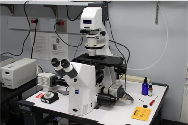
An optical microscope that has its conventional design reversed, with the objective lenses on the bottom and the light source and condenser on top, is known as an inverted microscope. Stated otherwise, the specimen is positioned above the stage, and light is shone through it in an upward direction.
Optical Path: An inverted microscope illuminates the specimen by directing the light path through the objective lenses from the top of the instrument downward. When working with large or bulky samples, this inverted shape makes it easier to access the specimen.
Objective Lenses: The objective lenses face upward toward the specimen and are situated beneath the stage. To meet a variety of imaging requirements, inverted microscopes usually come with a selection of objective lenses with varying magnifications and numerical apertures.
Stage: The stage of an inverted microscope is located above the objective lenses and holds the specimen in place for observation.
Condenser and Light Source: The condenser lens and light source are positioned above the stage to provide illumination for the specimen. The condenser focuses the light onto the specimen, while the light source (usually an adjustable halogen bulb or LED) provides uniform and adjustable illumination.
Eyepieces: The observer can view the magnified image of the specimen thanks to the eyepieces, also known as ocular lenses, which are situated at the top of the microscope. While some inverted microscopes feature monocular or trinocular eyepieces for digital imaging, others may include binocular eyepieces for stereo vision.
Focus Adjustment: Inverted microscopes typically have separate coarse and fine focus knobs or controls located on the side of the microscope. These controls allow the user to adjust the focus of the objective lenses to bring the specimen into sharp relief [44– 47].
Cell Culture and Live Cell Imaging: For seeing live cells and tissue cultures in cell culture dishes, inverted microscopes are perfect. The specimens are easily accessible for manipulation, imaging, and time-lapse microscopy because to the inverted architecture.
Microinjection and Micromanipulation: For micromanipulation procedures including laser microdissection, patch-clamp recording, and microinjection, inverted microscopes are frequently utilized. There is plenty of room to place micromanipulators, micro injectors, or other instruments above the specimen thanks to the inverted arrangement.
Limited Working Space: The working space may be limited by the inverted microscope’s design, which positions the objective lens beneath the specimen stage, particularly when working with large or tall specimens. This restriction can make it more difficult to manipulate samples or add extra tools like environmental chambers or micromanipulators.
Difficulty in Manipulating Coverslips: Inverted microscopes are frequently used to view materials that are placed on coverslips in multiwell plates or cell culture dishes. Because you have to reach underneath the stage to manipulate coverslips or access the sample, it can be difficult.
Limited Optical Performance for High Magnification: When compared to upright microscopes, inverted microscopes may perform less optically, particularly at high magnifications. Especially in applications involving fluorescence microscopy, the longer optical path length and intricate light path arrangements may result in lesser resolution, a lower numerical aperture, and worse image quality.
Accessibility for Maintenance: Compared to upright microscopes, inverted microscopes can be more difficult to reach for regular cleaning and maintenance. Because they may be hard to reach, parts under the stage may need to be disassembled or serviced with specialized equipment.
Cost: Inverted microscopes tend to be more expensive than upright microscopes due to their specialized design and construction. This higher cost can be a limiting factor for laboratories with budget constraints, particularly when considering the need for additional accessories or upgrades.
One of the most straightforward and widely used methods in optical microscopy for viewing transparent or pigmented specimens is bright field microscopy. Through eyepieces or a camera monitor, the observer examines the specimen against a bright background as it is illuminated from below by a bright light source in bright field microscopy. The bright field microscopy is used to visualize amplitude objects, that is, objects that contains a chromophore (an absorber), such as a hematoxylin and eosin stained tissue section or cell containing natural chromophore.
Light Source: A bright, consistent light source is placed underneath the specimen in bright field microscopy. LEDs, halogen lamps, and other illumination sources can be used as this light source. The light is focused onto the specimen after passing through a condenser lens system.
Condenser: The light is focused onto the specimen with the aid of the condenser lens system, which is situated underneath the stage. In order to maximize contrast and resolution, it might contain movable diaphragms or apertures that regulate the quantity and angle of light that reaches the specimen.
Objective Lenses: The specimen’s picture is magnified by the objective lenses, which are situated above it. Multiple objective lenses with varying magnification powers, from low to high, are commonly found in bright field microscopes. These lenses create the primary image by collecting light from the specimen.
Stage: The stage is a platform on which the specimen is placed for observation. It may have mechanical controls for precise positioning of the specimen under the objective lenses. The stage may also include specimen holders or clips to secure the specimen in place.
Eyepieces: The eyepieces, sometimes referred to as ocular lenses, are situated at the top of the microscope and enable the observer to see the specimen’s magnified picture. Stereo viewing is frequently accomplished with binocular eyepieces, which give a three-dimensional image of the object.
Low Contrast: In order to create contrast in specimens, bright field microscopy uses variations in light absorption and scattering. Nevertheless, a lot of biological specimens are transparent or have comparable refractive indices, which might lead to low contrast photos that are unclear and lacking in detail.
Limited Resolution: Bright field microscopy’s resolution is restricted by the objective lens’s numerical aperture and the illumination wavelength. This may make it more difficult to see intricate structures and details, particularly ones that are smaller than the wavelength of light.
Limited Specimen Compatibility: The best specimens for bright field microscopy are those that are dense enough to scatter or absorb light, like opaque materials or biological samples that have been stained. Under bright field illumination, it could be challenging to observe transparent or low contrast specimens.
Limited Depth of Field: Only a small portion of the material is always in focus when using bright field microscopy because it usually has a narrow depth of field. This can cause areas of the specimen to seem blurry, making it difficult to observe three-dimensional structures or specimens with uneven surfaces.
Artifact Formation: When imaging thick or highly refractive specimens, bright field microscopy can create artifacts including diffraction patterns, glare, and halos. These artifacts can make it more difficult to understand the photos and hide information in the material.
Limited Capability for Live Cell Imaging: Because of the low contrast and possible phototoxicity of bright field illumination, bright field microscopy is frequently not appropriate for live cell imaging. It may be challenging to follow cellular motions or notice minute morphological changes over time because to the absence of contrast.
Sample Preparation Requirements: Bright field microscopy often requires specimens to be stained or fixed to enhance contrast and visibility. This can introduce artifacts or alter the natural properties of the specimen, limiting its suitability for certain applications, such as live cell imaging or observation of unstained specimens.
To enhance contrast and visibility, bright field microscopy can be combined with various staining techniques, such as simple stains (e.g., methylene blue, crystal violet) or differential stains (e.g., Gram stain), which selectively color different structures or components of the specimen.
An optical microscopy method called dark field microscopy is used to view transparent or translucent materials, including bacteria, tiny creatures, and living cells. Dark field microscopy uses oblique or off-axis light to illuminate the specimen, making it look bright against a dark background, in contrast to bright field microscopy, which shows the specimen against a bright background. High contrast is produced, making the specimen’s minute details and structures easier to see.
Light Source: An optical microscopy method called dark field microscopy is used to view transparent or translucent materials, including bacteria, tiny creatures, and living cells. Dark field microscopy uses oblique or off-axis light to illuminate the specimen, making it look bright against a dark background, in contrast to bright field microscopy, which shows the specimen against a bright background. High contrast is produced, making the specimen’s minute details and structures easier to see.
Condenser: A dedicated dark field condenser in the condenser lens system, which is situated underneath the stage, focuses oblique light onto the specimen. To maximize contrast and resolution, the condenser may feature movable diaphragms or apertures that regulate the oblique light’s angle and intensity.
Objective Lenses: The specimen’s picture is magnified by the objective lenses, which are situated above it. Multiple objective lenses with varying magnification powers, from low to high, are commonly found in dark field microscopes. The principal image is created by these lenses collecting light that is scattered by the object.
Stage: The specimen is positioned for observation on the stage, which is a platform. For accurate specimen placement beneath the objective lenses, it might have mechanical controls. Additionally, the stage could have clips or specimen holders to retain the specimen in place.
Eyepieces: The eyepieces, sometimes referred to as ocular lenses, are situated at the top of the microscope and enable the observer to see the specimen’s magnified picture. Stereo viewing is frequently accomplished with binocular eyepieces, which give a three-dimensional image of the object.
Focus Adjustment: Separate coarse and fine focus knobs or settings are usually found on the side of dark field microscopes, as seen in Figure 10. By using these controls, the user can bring the specimen into crisp relief by adjusting the objective lenses’ focus.
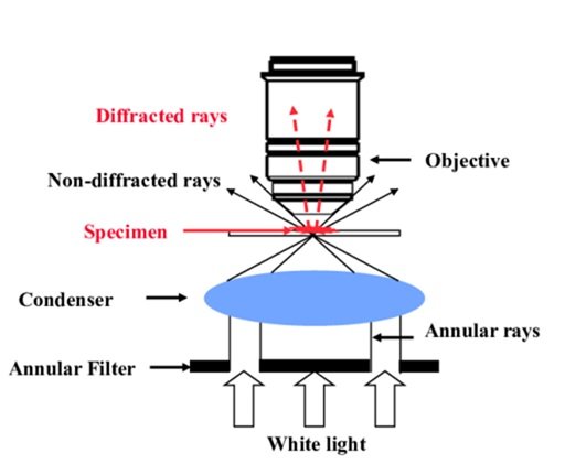
Without the requirement for staining or labeling, phase contrast microscopy is an optical microscopy technique that improves the contrast of translucent or semi-transparent objects, such as living cells, tissues, and thin sections. In order to create variations in brightness or contrast in the final image, it takes use of the phase variances in light waves as they travel through various areas of the specimen.
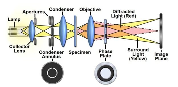
Phase Plate: The phase plate, a specialized optical element that adds a phase shift to the light traveling through the specimen to create contrast between areas of different optical densities, is the essential part of phase contrast microscopy. It is situated in the optical pathway of the microscope.
Condenser: Specialized phase contrast annuli or rings that correspond to the phase shift brought about by the phase plate are part of the condenser lens system, which is situated underneath the stage. Phase contrast is created by these annuli, which change the light source’s uniform illumination into a hollow cone of light that interacts with the specimen.
Objective Lenses: The specimen’s picture is magnified by the objective lenses, which are situated above it. In order to maximize contrast and resolution at various magnifications, phase contrast microscopes usually feature numerous phase contrast objectives with matching phase annuli.
Phase Ring: In addition to the phase plate and condenser annuli, phase contrast microscopy requires a phase ring in each objective lens to match the phase shift introduced by the phase plate. These phase rings are positioned in the objective lenses and help to convert the phase differences in the specimen into visible contrast in the final image.
Eyepieces: The eyepieces, sometimes referred to as ocular lenses, are situated at the top of the microscope and enable the observer to see the specimen’s magnified picture. Stereo viewing is frequently accomplished with binocular eyepieces, which give a three-dimensional image of the object.
Focus Adjustment: The phase contrast microscope is depicted below in Figure 11 and usually has distinct coarse and fine focus knobs or controls on the side of the microscope that allow the user to adjust the focus of the objective lenses to bring the specimen into sharp relief.
Resolution Limitations: Beyond light microscopy’s diffraction limit, phase contrast microscopy does not automatically increase resolution. While it boosts contrast, it may not provide the same amount of information as other microscopy techniques such as electron microscopy.
Halo Effect: Phase contrast microscopy has the ability to create a halo effect around the margins and boundaries of internal structures. Especially at high magnifications, this aberration may make it difficult to correctly interpret photos and obscure small features.
Halo Reduction with Thick Specimens: The halo effect may intensify when imaging thicker specimens, lowering the quality of the image as a whole. When examining dense samples or three-dimensional structures, this could be a drawback.
Phase Shift Variation: The phase shift induced by phase contrast optics is dependent on the wavelength of light, meaning that different colors of light can produce changes in contrast and image quality. This can lead to color fringing or inconsistencies in image appearance, especially in multi-channel imaging.
Sample Preparation Requirements: While phase contrast microscopy may view unstained specimens, it may still require meticulous sample preparation to enhance contrast and image quality. The efficiency of phase contrast imaging can be affected by the thickness of the specimen, the refractive index, and the mounting medium.
This technique is based on the fact that light passing through one material and into another material of slightly different refractive index will suffer a shift in phase. These wave-front inconsistencies or differences in phase are translated into changes in the structure’s brightness, which makes them visually appealing. Differences in cells and their architecture that cannot be explained by other microscopic material can be seen with phase contrast microscopy [48, 49].
Confocal microscopy is an advanced optical imaging technique used to obtain high-resolution, three-dimensional images of biological specimens with exceptional clarity and contrast.
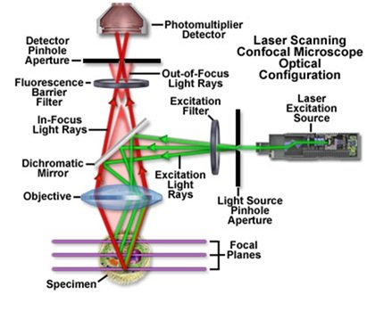
Laser Light Source: Confocal microscopes offer bright, consistent illumination by using a laser light source, usually a high-intensity laser like an argon or helium-neon (HeNe) laser. A narrow beam of laser light is concentrated and moved in a raster pattern across the material.
Scanning System: The laser beam is quickly guided across the specimen in the x, y, and z dimensions by mirrors or galvanometers that make up the scanning system. The location and depth of the lighted focal point within the specimen may be precisely controlled thanks to this scanning procedure.
Objective Lens: The objective lens is in charge of directing the laser beam onto the sample and gathering any reflected or fluorescence light that is released. High numerical aperture (NA) objective lenses with excellent light-gathering efficiency and spatial resolution are commonly used in confocal microscopes.
Pinhole Aperture: The pinhole aperture, which is placed in front of the detector to selectively capture light emitted from the lit focal point while rejecting out-of-focus light, is one of the essential parts of a confocal microscope. Only light coming from the focus plane can pass through the pinhole aperture, which serves as a spatial filter.
Detector: To record the fluorescence or reflected light that the specimen emits, confocal microscopes are fitted with sensitive photodetectors, such as avalanche photodiodes (APDs) or photomultiplier tubes (PMTs). Incoming light signals are transformed into electrical signals by the detector, which subsequently processes and transforms them into digital images.
Image Reconstruction Software: Confocal microscopes are controlled by specialized software that orchestrates the scanning process, controls the laser and detector parameters, and reconstructs the acquired image data into three-dimensional (3D) images or image stacks. Advanced image processing algorithms may be used to enhance image quality, reduce noise, and improve resolution [50– 55].
Confocal microscopy offers several advantages over conventional wide field microscopy:
Confocal microscopy is widely used in various fields of biological research, including cell biology, neuroscience, developmental biology, immunology, and microbiology. It is instrumental in studying.
Reduced Background Noise: By rejecting out-of-focus light using the pinhole aperture, confocal microscopy produces images with significantly reduced background noise and improved contrast, especially in thick or densely labeled specimens.
Live Cell Imaging: Because confocal microscopy can record dynamic events in real time with no photobleaching or phototoxicity, it is ideally suited for live cell imaging studies. Subcellular features, cellular dynamics, tissue shape, and protein localization inside biological specimens can all be tracked over time thanks to the capacity to selectively illuminate particular focal planes. Confocal microscopy is also used for imaging and analysis in materials science, drug development, and medical diagnostics.
Cost: Confocal microscopes are typically more expensive than conventional wide-field microscopes due to their complex design and specialized components.
Complexity: A certain amount of skill is needed to operate and understand the results from confocal microscopy. The microscope can be difficult to set up and position, and it may take specialized knowledge to optimize imaging parameters including laser power, pinhole size, and detector settings.
Slow Imaging Speed: Since confocal microscopy takes pictures point by point, it is typically slower than wide-field microscopy. This could lead to prolonged acquisition periods and possible photobleaching or phototoxicity effects on live samples, which could be a drawback when imaging dynamic processes or broad areas.
Limited Depth Penetration: Although confocal microscopy offers superior optical sectioning capabilities, its capacity to scan deeply into thick materials is constrained. At deeper optical planes, the penetration depth may be lowered due to light scattering and sample absorption, which would lower the signal-to-noise ratio and image quality.
Sample Preparation Requirements: In order to reduce background fluorescence and autofluorescence, which can degrade image quality, confocal microscopy frequently necessitates meticulous sample preparation. Procedures including fixing, staining, and mounting can be required, which could change the specimen’s natural characteristics or introduce artifacts.
Limited Compatibility with Certain Samples: Because of their optical characteristics or compatibility with fluorescent dyes, some samples might not be appropriate for confocal microscopy. For instance, substances that are highly scattering or opaque could be challenging to image with confocal microscopy or yield images of low quality.
Photo-toxicity and Photo-bleaching: Confocal microscopy typically requires high-intensity laser illumination, which can induce photo-toxicity and photo-bleaching in live samples.
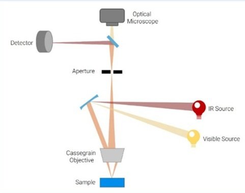
It is a sophisticated imaging method that visualizes and analyzes material with high sensitivity and specificity using infrared (IR) radiation. Since infrared radiation has longer wavelengths and can reach deeper into materials than visible light, which is utilized in conventional optical microscopes, it can reveal important details about the chemical makeup, structure, and characteristics of materials [56– 60].
The basic idea behind infrared microscopy is to find out whether a sample is absorbing, transmitting, or reflecting infrared light. After the sample is exposed to infrared light, the light’s interaction with the sample results in distinctive absorption spectra that reveal the molecular makeup and structure of the sample. A detector to record the infrared signal, optical components to focus and direct the light onto the sample, and an infrared light source make up the microscope. In order to produce spatially resolved infrared images, the detector gauges the amount of infrared light that is transmitted through or reflected from the sample [61].
Transmission Mode: The sample in transmission infrared microscopy is sufficiently thin to permit the passage of infrared light through it. To learn more about the molecular makeup and structure of the sample, the transmitted light is gathered and examined. Thin films, polymers, tissues, and biomolecules are all frequently studied using transmission infrared microscopy in the fields of materials science, chemistry, and biology.
Reflection Mode: Infrared light is shone onto the sample’s surface in reflection infrared microscopy, and the reflected light is then gathered and examined. Metals, ceramics, and painted surfaces are examples of opaque or thick materials that can be examined using reflection infrared microscopy.
Attenuated Total Reflection (ATR) Mode: In order to increase the sensitivity of infrared spectroscopy for examining liquid or solid samples in contact with the crystal surface, ATR infrared microscopy uses a unique crystal or prism to create an evanescent wave at the sample interface. Chemical analysis, surface science, and pharmaceuticals all make extensive use of ATR infrared microscopy. Figure 13 displays the Infrared Microscope’s equipment.
Chemical Analysis: Infrared microscopy is extensively used for chemical analysis and identification of organic and inorganic compounds based on their unique infrared absorption spectra. It is employed in pharmaceuticals, forensics, environmental science, and food science for qualitative and quantitative analysis of samples.
Materials Characterization: Infrared microscopy provides valuable insights into the chemical composition, structure, and properties of materials such as polymers, composites, minerals, and nanomaterials. It is used to study defects, interfaces, phase transitions, and degradation.
Biomedical Research: mechanisms in materials science and engineering.
Infrared microscopy plays a vital role in biomedical research for studying biological tissues, cells, and biomolecules.
Pharmaceutical Development: Infrared microscopy is utilized in pharmaceutical development for analyzing drug formulations, detecting impurities, and monitoring drug release kinetics. It facilitates quality control, formulation optimization, and stability testing of pharmaceutical products.
Chemical Specificity: The working principle of Infrared Microscopy is based on IR Spectroscopy, which is used for the identification of various functional groups in organic and inorganic compounds. Here we get characteristic spectra based upon their absorption in IR region.
Non-destructive Analysis: Infrared microscopy is non-destructive and can analyze samples in their native state.
High Sensitivity: Infrared microscopy is highly sensitive and can detect even trace amounts of compounds.
Spatial Resolution: Infrared microscopy provides spatially resolved images with micrometer-scale resolution, allowing for detailed visualization and analysis of sample morphology and composition.
Limited Spatial Resolution: The spatial resolution of infrared microscopy is typically lower than that of visible light microscopy due to the longer wavelength of infrared radiation.
Limited Spectral Range: Infrared microscopy is generally limited to a specific range of infrared wavelengths, typically between mid-infrared (MIR) and near-infrared (NIR) regions.
Sample Preparation Requirements: Pharmaceutical development uses infrared microscopy to monitor drug release kinetics, analyze drug formulations, and identify contaminants. It makes pharmaceutical product stability testing, formulation optimization, and quality control easier.
Limited Depth Profiling: Mostly a surface-sensitive method, infrared microscopy has little ability to penetrate deeply into the sample. When examining thick or multi-layered materials, this can be a drawback because infrared light might not be able to pass through the surface layers efficiently, producing inaccurate or skewed results.
Equipment Cost and Complexity: Infrared microscopy systems can be expensive to purchase and maintain, requiring specialized equipment such as infrared light sources, detectors, and optics. The complexity of infrared instrumentation and the need for expertise in infrared spectroscopy techniques can also be barriers to adoption.
This is modern advanced technique for imaging which uses electromagnetic radiations in the ultraviolet region. As ultraviolet radiation lies below the wavelength region of visible region, it is much energetic and can analyze the sample with high resolution and sensitivity.
The working principle of UV Microscopy is based upon the interaction between ultraviolet light and sample under study. As a result of interaction between ultraviolet radiation and sample, phenomenon of fluorescence, phosphorescence, absorption, scattering phenomenon can take place. By successful detection of such phenomenon, UV microscope can provide information regarding the image of the sample under study, chemical composition, structure and properties of the sample. The microscope consists of a UV light source, optical components for focusing and directing the UV light onto the sample, and a detector for capturing the UV signal. The detector measures the intensity of UV radiation emitted, absorbed, or scattered by the sample, generating high-resolution images with detailed spatial information.
There are three main types of Ultraviolet microscope as furnished below:
Fluorescence Microscopy: The most popular type of UV microscopy is fluorescence microscopy. The material is either tagged or fluoresces naturally under UV illumination in fluorescence microscopy, releasing visible light at longer wavelengths. High contrast and sensitivity fluorescence images are produced by gathering and detecting this released light. In order to study cellular architecture, protein localization, molecular interactions, and dynamic processes in living cells and tissues, fluorescence microscopy is extensively employed in the fields of cell biology, molecular biology, immunology, and neurology.
Absorption Microscopy: In absorption microscopy, the amount of UV light absorbed by the material is measured. The optical characteristics, chemical makeup, and concentration of absorbing compounds in the sample can all be determined using absorption microscopy. Thin films, nanoparticles, polymers, and organic substances are all analyzed using it in the fields of materials science, chemistry, and environmental science.
Reflectance Microscopy: Reflectance microscopy quantifies how much UV light is reflected off the surface of the sample. Materials including metals, ceramics, and semiconductors can have their surface morphology, texture, and optical characteristics examined using reflectance microscopy.
Life Sciences: In biological research, ultraviolet microscopy is frequently used to examine biological processes, molecular interactions, and cellular structures. It is used to image cells, tissues, organelles, proteins, and nucleic acids in the fields of cell biology, microbiology, genetics, and neurology.
Materials Science and Nanotechnology: In materials science and nanotechnology, ultraviolet microscopy is essential for examining surfaces, interfaces, thin films, and nanomaterials.
High Sensitivity: Ultraviolet microscopy offers great sensitivity and specificity, enabling detection of fluorescent labels, biomolecules, and trace compounds with low concentrations.
Selective Excitation: Fluorophores and fluorescent probes are selectively excited by ultraviolet microscopy, allowing for the selective imaging of particular targets in complex materials.
High Resolution: The viewing of tiny structures and features at the subcellular and nanoscale scale is made possible by ultraviolet microscopy, which produces high-resolution images with precise spatial information.
Chemical Specificity: Ultraviolet microscopy offers chemical specificity, allowing for identification and characterization of samples based on their fluorescence properties, absorption spectra, and surface reflectance.
Sample Preparation: Some samples may require specific preparation techniques, such as staining or labeling with fluorescent markers, to enhance contrast or make certain features visible under UV light. This preparation can be time-consuming and may alter the sample’s original properties.
Damage to Biological Samples: Prolonged exposure to UV light can cause damage to biological samples, including DNA damage and photobleaching of fluorescent markers. This can affect the integrity of the sample and limit the duration of observation.
Limited Field of View: UV microscopy often has a shorter field of vision compared to visible light microscopy, which can make it tough to study large samples or structures that require a wide field for context.
Limited Availability of UV-Compatible Optics: Not all microscope systems are tuned for UV imaging, and UV-compatible optics may be more expensive or less easily accessible compared to those developed for visible light microscopy.
Chromatic Aberration: UV light can exhibit stronger chromatic aberration compared to visible light, leading to distortions in the image and reduced clarity, particularly in high-magnification applications.
Background Noise: UV light can exhibit stronger chromatic aberration compared to visible light, leading to distortions in the image and reduced clarity, particularly in high-magnification applications.
Health and Safety Considerations: UV rays can be hazardous to the eyes and skin if necessary precautions are not taken. Users must make sure they are taking the proper precautions, such as avoiding direct UV light exposure and donning UV-blocking goggles.
Because it makes it possible to see and describe things at the micro- and nanoscale, microscopy has completely changed how we perceive the world. Numerous microscope varieties, each founded on distinct principles, provide special capabilities and are used in a wide range of scientific and technological domains. According to the underlying concept, there are several types of microscopes, including optical, electron, probe, and scanning thermal microscopy. Microscopy developments keep pushing the limits of scientific inquiry and enabling breakthroughs and discoveries in many fields. Microscopy continues to be a vital tool for scientific research and technological development, from solving the secrets of the subcellular realm to creating new materials with specific qualities.
Through the viewing and characterization of things at the micro- and nanoscale, microscopy has completely changed our understanding of the world around us. particular kinds of microscopes, each founded on a particular set of principles, have special strengths and are used in a wide range of scientific and technological domains. The idea allows for the classification of microscopes into many categories, including scanning thermal microscopy, optical, electron, and probe microscopes. Innovations and discoveries in many fields are made possible by advances in microscopy, which keep pushing the limits of scientific investigation. From solving the enigmas of the subcellular realm to creating novel materials with specific characteristics, microscopy continues to be a vital instrument for scientific research and technological development.
In the recent past there has been rapid change in the characterization techniques for biological and nanomaterials. Also the existing technique has advanced due to adaptation of new technology. In the last section we have discussed various applications of materials at nanoscale especially their uses in veterinary science and agriculture.