
Effective heat transfer in fluid flow systems is essential for thermal management in various engineering fields, such as microfluidic devices [1– 3], aerospace parts [4], energy systems, cooling units [5– 9], and chemical reactors [10]. In these systems, fluid movement, especially shear-driven flows, significantly influences thermal performance [11]. Traditional no-slip and fixed-wall temperature assumptions often do not accurately depict real interfaces, particularly at microscales or on surfaces covered with rarefied gases. In such cases, velocity slip becomes important in microchannels or flows over hydrophobic boundaries [12– 15]. Similarly, convective boundary conditions offer a more precise way to model heat exchange when a solid boundary thermally interacts with an external fluid environment [14, 16, 17].
Magnetohydrodynamic (MHD) flows through porous domains have attracted considerable interest due to their relevance in power generation, metallurgy, geothermal extraction, nuclear cooling, and electromagnetic pumping systems. The application of a magnetic field introduces Lorentz forces that alter velocity distributions and heat transfer characteristics, while the presence of a porous structure introduces additional flow resistance [15]. These combined effects strongly influence momentum transport, temperature fields, and energy dissipation, making their study important in thermofluid management involving electrically conducting fluids.
Several recent studies have explored various methods to improve heat transfer efficiency. Kumar and Pathak [18] found that increasing slip length decreases heat transfer between dispersed and continuous phases in a microfluidic T-junction. Rashad et al. [16] observed that Biot and Eckert numbers raise temperature profiles while reducing heat transfer, and that convective boundary conditions and thermal radiation increase surface friction. Shahzad et al. [17] showed that platelet-shaped Cu nanoparticles optimize heat transfer in thin-film flows with slip and convective boundaries. Jan et al. [19] examined ternary hybrid nanofluids with variable thermal conductivity on stretching sheets under convective and magnetic effects. Vinodkumar et al. [20] emphasized the importance of MHD transport in power generation, thermal management, sensors, and biomedical flows, noting that Biot number and suction promote heat transfer, while Brownian motion, thermophoresis, and thermal relaxation hinder it. Other studies [21– 27] investigated non-Newtonian behavior, Darcy–Forchheimer resistance, radiative heat flux, and slip phenomena, consistently highlighting how boundary interactions and fluid properties influence heat transfer.
Minimizing thermodynamic losses is equally essential in thermal system design, and entropy generation offers a quantitative measure of such irreversibilities [28– 30]. The choice of boundary condition (convective, isothermal, adiabatic, isoflux, etc.) significantly shapes temperature gradients, heat dissipation, and trends in the Bejan number [31, 32]. The classical no-slip condition becomes inadequate at micro-scales, whereas the Navier slip condition permits partial velocity slip and can substantially alter both flow and heat transfer behavior [12, 13]. Following Bejan’s foundational contributions [29, 33], entropy generation analysis has been applied to various configurations and boundary conditions, with studies confirming that suction/injection, magnetic fields, slip, and thermal boundary interactions jointly influence velocity, temperature, and entropy distributions. However, despite extensive work, limited attention has been given to setups that incorporate Navier slip, suction/injection, and mixed thermal boundary conditions in MHD porous-wall channels. In view of this, Samantaray et al. [35] and others [36– 40] have extended the entropy generation study to composite nanofluids.
Although entropy generation in magnetohydrodynamic (MHD) flows through porous media and impermeable-wall channels has been widely studied, substantially fewer investigations consider porous walls in conjunction with Navier slip, convective or mixed thermal boundary conditions, and entropy generation analysis. Most existing works examine these mechanisms in isolation, such as slip effects, suction or injection, Darcy resistance, or magnetic field influence, thereby providing limited insight into their coupled impact on flow structure, heat transfer, and thermodynamic irreversibility [41– 46]. Prior studies have demonstrated that magnetic fields, porosity, wall slip, thermal radiation, viscous dissipation, and Joule heating significantly modify entropy generation and Bejan number behaviour under specific configurations [47– 50]. However, analyses that simultaneously account for wall permeability, Navier slip, magnetic effects, and contrasting thermal boundary conditions remain scarce. Notably, only a limited number of studies have addressed MHD porous channel flows with Navier slip under differing thermal boundary constraints, with or without Joule dissipation. This gap motivates a unified investigation that clarifies how wall permeability, slip, magnetic fields, and external convection jointly govern heat transfer performance and thermodynamic irreversibility.
The primary objective of the present study is to analytically investigate steady MHD flow in a channel with porous walls, incorporating Navier slip and convective thermal boundary conditions along with internal heat generation or absorption. The analysis examines how magnetic field intensity, suction/injection velocity, slip coefficients, Biot number, and heat source/sink parameters affect velocity, temperature, and entropy-generation characteristics. By explicitly modeling wall permeability rather than a uniformly porous medium, this study clarifies the mechanisms through which porous-wall mass transfer influences flow behavior and thermodynamic losses. The resulting insights provide quantitative guidance for designing microfluidic, porous-wall, and energy-conversion systems where slip and convective interactions are important for thermal optimization.
We consider a steady, viscous, incompressible, and electrically conducting fluid flow confined between two horizontal porous walls separated by a fixed distance \(h\). The upper wall is maintained at a prescribed temperature (isothermal condition), while a convective heating boundary condition is imposed at the lower wall. The coordinate system is defined such that the \(x-\) axis runs parallel to the walls in the direction of the flow, while the \(y-\) axis is oriented perpendicular to the walls.
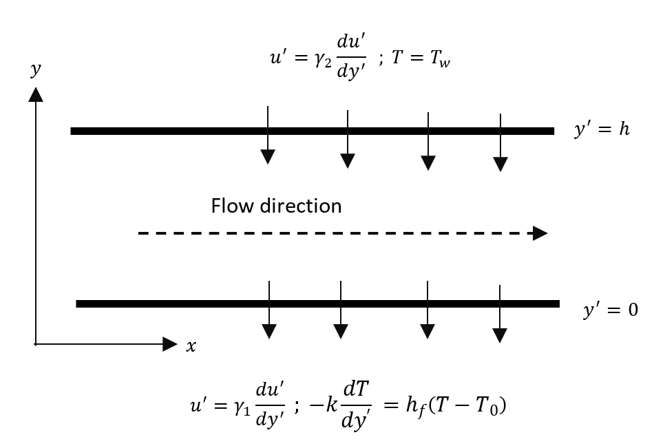
Figure 1 schematically illustrates the flow configuration, where the fluid moves steadily along the \(x-\)direction, and a uniform transverse magnetic field is applied normal to the walls. The presence of this magnetic field introduces magnetohydrodynamic (MHD) effects that influence the flow and heat transfer characteristics within the channel. The basic equations governing the flow are:
Conservation of mass: \[\label{GrindEQ__1_} \mathrm{\nabla }\bullet \overrightarrow{V}=0 . \tag{1}\]
Conservation of momentum: \[\label{GrindEQ__2_} \rho \left(\frac{\partial \overrightarrow{U}}{\partial t}+(\overrightarrow{V}\bullet \mathrm{\nabla })\overrightarrow{V}\right)=-\mathrm{\nabla }P+\ \mu {\mathrm{\nabla }}^2\overrightarrow{V}+\ \overrightarrow{F} . \tag{2}\]
Conservation of energy: \[\label{GrindEQ__3_} \frac{\partial T}{\partial t}+\left(\overrightarrow{V}\bullet \mathrm{\nabla }\right)T=\frac{k}{\rho c_p}{\mathrm{\nabla }}^2T+\ \frac{J.J}{\sigma}+\Phi , \tag{3}\] where \(\mathrm{\nabla }=\frac{\partial }{\partial x}\widehat{i\ }+\frac{\partial }{\partial y}\widehat{j\ }+\frac{\partial }{\partial z}\widehat{k\ }\). The physical quantities \(\rho ,\ v,\ c_p,\overrightarrow{F},\ \overrightarrow{V},\ T\), \(\frac{J.J}{\sigma},\ \Phi \mathrm{,\ }\)and \(k\) are all defined in the nomenclature, and since the flow is steady, \(\frac{\partial \overrightarrow{U}}{\partial t}=0\) in Eq. (2).
A 2-dimensional flow is considered so that \(\overrightarrow{V}=(u,\ v,\ 0)\), where \(u\) and \(v\) are the horizontal and vertical components of velocity, respectively. The flow is fully developed, and all physical variables except pressure depend only on \(y\) so that Eq. (1) becomes: \[\label{GrindEQ__4_} \frac{\partial v}{\partial y}=0 . \tag{4}\]
Integrating Eq. (4), we have the vertical velocity as \(v={-v}_0\) (a constant) which is the suction/injection velocity on the wall \(y'=h\).
The dimensional governing momentum and energy equations for the steady flow of viscous incompressible fluid in the presence of a magnetic field, heat source/sink, and Joule heating with associated boundary conditions are given by: \[\label{GrindEQ__5_} \mu \frac{d^2u'}{dy^{'2}}-\rho \nu_0\frac{du'}{dy'}-\sigma B^2_0u'=-\frac{\partial P}{\partial x} , \tag{5}\] \[\label{GrindEQ__6_} k\frac{d^2T}{dy^{'2}}-\rho C_p\nu_0\frac{dT}{dy}-Q_0\left(T-T_0\right)+\mu {\left(\frac{du'}{dy'}\right)}^2+\lambda \sigma B^2_0u^{'2}=0 , \tag{6}\] where \(u',\ y',\ B_0,\ \sigma,\ \rho ,\ c_p,\ \mu ,\ v_0\) and \(\lambda\) are all defined in the nomenclature. The index \(\lambda\) in Eq. (6) is set equal to 0 for excluding Joule dissipation and 1 for including Joule dissipation.
The boundary conditions associated with this problem are: \[u'=\gamma_1\frac{du'}{dy'}\ \ \ ;\ \ -k\frac{dT}{dy'}-h_f\left(T-T_0\right)=0\ \ \ \ \ at\ \ \ \ \ y'=0,\] \[\label{GrindEQ__7_} u'=\gamma_2\frac{du'}{dy'}\ \ \ ;\ \ T=T_h\ \ \ \ \ \ \ \ \ \ at\ \ \ \ \ y'=h , \tag{7}\] where \(\gamma_1\) and \(\gamma_2\) are the slip coefficients.
The non-dimensional quantities for the above equations are defined as: \[\begin{aligned} \label{GrindEQ__8_} \theta =&\frac{{T-T}_0}{T_h-T_0} ; \ y=\frac{y'}{h} ; u=\frac{u'}{\nu_0}\ ; M^2=\frac{\sigma B^2h^2}{\rho \nu}\ ; Br=\frac{\mu \nu^2_0}{k(T_h-T_0)}\ ; Pe=\frac{\nu_0h\rho c_p}{k} ; Re=\frac{\nu_0h}{\nu} ;\notag\\ P=&\frac{h^2}{\rho \nu\nu_0}\left(-\frac{\partial P}{\partial x}\right) \beta_1=\frac{\gamma_1}{h} ; \beta_2=\frac{\gamma_2}{h} ; H=\frac{Q_0h^2}{k} . \end{aligned} \tag{8}\]
As a consequence of applying Eqs. (8) to Eqs. (5) – (7), the dimensional form of the momentum and energy equations reduces to: \[\label{GrindEQ__9_} \frac{d^2u}{dy^2}-Re\frac{du}{dy}-M^2u=-P , \tag{9}\] \[\label{GrindEQ__10_} \frac{d^2\theta }{dy^2}-Pe\frac{d\theta }{dy}-H\theta +Br\left[{\left(\frac{du}{dy}\right)}^2+\lambda M^2u^2\right]=0 . \tag{10}\]
With boundary conditions: \[u=\beta_1\frac{du}{dy}\ \ \ ;\ \ \ \frac{d\theta }{dy}+Bi\theta =0 \ \ at\ \ \ \ \ \ y=0,\] \[\label{GrindEQ__11_} u=\beta_2\frac{du}{dy}\ \ \ ;\ \ \theta =1 \ \ at\ \ \ \ \ \ y=h , \tag{11}\] where \(\beta_1\) and \(\beta_2\) are the slip parameters.
The solution to Eq. (9) subject to the boundary condition in (11) is: \[\label{GrindEQ__12_} u\left(y\right)=\frac{P}{M^2}\mathrm{+}\left[X_1Cosh(ry)+Y_1Sinh(ry)\right]e^{\frac{Re}{2}y} , \tag{12}\] where \(X_1\), \(Y_1\) and \(r\) are given in the appendix.
The solution in Eq. (12) exists for both \(Re<0\) which corresponds to blowing (injection) at the walls and \(Re>0\) which corresponds to suction at the walls, respectively.
On the use of Eq. (12), Eq. (10) is refined as: \[\begin{aligned} \label{GrindEQ__13_} &\frac{d^2\theta }{dy^2}-Pe\frac{d\theta }{dy}-H\notag\\ &=-Br\left[e^{Rey}\left\{Z_1Cosh^2(ry)+Z_2Sinh^2(ry)+Z_3Cosh(ry)Sinh(ry)\right\}+e^{\frac{Re}{2}y}\left\{Z_4Cosh(ry)+Z_5Sinh(ry)\right\}+\frac{\lambda P^2}{M^2}\right] . \end{aligned} \tag{13}\]
The solution for Eq. (13) subject to the boundary condition in Eq. (11) is given as: \[\begin{aligned} \label{GrindEQ__14_} &\left[C_1Cosh\left(\eta y\right)+C_2Sinh(\eta y)\right]e^{\frac{Pe}{2}y}\notag\\ &-Br\left[e^{Rey}\left\{Y_2+Y_3Cosh\left(2ry\right)+Y_4Sinh(2ry)\right\}+e^{\frac{Re}{2}y}\left\{Y_5Cosh\left(ry\right)+Y_6Sinh(ry)\right\}-X_{14}\right] , \end{aligned} \tag{14}\] where \(\eta\), \(Y_2,\ Y_3,\ Y_4,\ Y_5,\ Y_6,Z_1,Z_2,Z_3,Z_4,Z_5,\ C_1\),\(C_2\) and \(X_{14}\) are provided in the appendix.
Two important flow performance parameters, namely the skin friction \((\tau)\) and mass flow rate \(\overline{Q}\) and an important transport characteristic, namely the Nusselt number \((Nu)\) are obtained below.
Using Eq. (8), the skin friction \((\tau)\) is obtained by direct differentiation at \(y=0\) and \(y=1\) and it is given as: \[\label{GrindEQ__15_} \tau_1={\left.\frac{du}{dy}\right|}_{y=0}=rY_1+\frac{ReX_1}{2} , \tag{15}\] \[\label{GrindEQ__16_} \tau_2={\left.\frac{du}{dy}\right|}_{y=1}=\left[\left(rX_1Sinh\left(r\right)+rY_1Cosh\left(r\right)\right)+\frac{Re}{2}\left(X_1Cosh\left(r\right)+Y_1Sinh\left(r\right)\right)\right]e^{\frac{Re}{2}} . \tag{16}\]
Integrating Eq. (8) over 0 and 1 gives the mass flux rate \(\overline{Q}\) which is: \[\label{GrindEQ__17_} \overline{Q}=\int^1_0{u\left(y\right)dy=}\left(\frac{X_1+Y_1}{2}\right)\left[\frac{1}{r+\frac{Re}{2}}\left(e^{\left(r+\frac{Re}{2}\right)}-1\right)\right]+\left(\frac{X_1-Y_1}{2}\right)\left[\frac{1}{\frac{Re}{2}-1}\left(e^{\left(\frac{Re}{2}-1\right)}-1\right)\right]+\frac{P}{M^2} . \tag{17}\]
The rate of heat transfer (Nusselt number) at the lower and upper plates is obtained by differentiating Eq. (13) at \(y=0\) and \(y=1\) respectively, and it is given as: \[\label{GrindEQ__18_} {Nu}_0={\left.\frac{d\theta }{dy}\right|}_{y=0}=\eta C_2+\frac{PeC_1}{2}-\Psi_3 , \tag{18}\] \[\label{GrindEQ__19_} {Nu}_1={\left.\frac{d\theta }{dy}\right|}_{y=1}=\left[C_1Cosh\left(\eta \right)+C_2Sinh(\eta )\right]e^{\frac{Pe}{2}}-\Psi_4 , \tag{19}\] where \(\Psi_3\) and \(\Psi_4\) are given in the appendix.
The examination of entropy within fluid flow is a consequence of inherent irreversibility, originating from factors like heat transfer, frictional dissipative processes, and others within the model. The overall entropy of an isolated system either remains constant or increases, never decreasing, according to the second law of thermodynamics. Given that entropy generation is linked to the dissipation of energy in various technical and industrial operations, accurately estimating the rate of entropy generation within the system is of paramount importance [51]. For a viscous, incompressible, and electrically conducting fluid subjected to a magnetic field, the local volumetric rate of entropy generation, \(E_G\) as formulated by Woods [52] is given by: \[\label{GrindEQ__20_} E_G=\frac{K}{T^2_0}{\left(\frac{dT}{dy'}\right)}^2+\frac{\mu }{T_0}{\left(\frac{du'}{dy'}\right)}^2+\lambda \frac{\sigma B^2_0}{T_0}{u'}^2 . \tag{20}\]
The first term in Eq. (20) accounts for the entropy generation due to heat transfer, the second term accounts for viscous dissipation, and the third term accounts for entropy production resulting from the magnetic field effects (Joule or Ohmic heating).
The entropy generation number, \(Ns\) is a key dimensionless parameter that quantifies the extent of entropy produced within a system as a result of inherent irreversibilities. In practical applications, these irreversibilities stem from mechanisms such as heat transfer, fluid friction, viscous dissipation, and Joule heating, effects that are especially significant in magnetohydrodynamic (MHD) flows. The dimensional form of the entropy generation number can be expressed as: \[\label{GrindEQ__21_} Ns=\frac{T^2_0h^2E_G}{k{\left(T_h-T_0\right)}^2} . \tag{21}\]
Recasting this into dimensionless variables, using dimensionless velocity \((u)\), temperature \((\theta )\), and other key parameters, we obtain: \[\label{GrindEQ__22_} Ns={\left(\frac{d\theta }{dy}\right)}^2+\frac{Br}{\Omega}\left[{\left(\frac{du}{dy}\right)}^2+\lambda M^2u^2\right] , \tag{22}\] where \(Br=\frac{\mu \nu^2_0}{k(T_h-T_0)}\) is the Brinkmann number, \(\Omega=\frac{T_h-T_0}{T_0}\) is the non-dimensional temperature difference, and \(M^2=\frac{\sigma B^2_0h^2}{\rho \nu}\) is the magnetic parameter. The entropy generation number can be written as a summation of the entropy generation due to heat transfer, denoted by \(N_h\) and the entropy generation due to the combined effects of fluid friction and magnetic field, denoted by \(N_f\) i.e., \(N_h={\left(\frac{d\theta }{dy}\right)}^2\) and \(N_f=\frac{Br}{\Omega}\left[{\left(\frac{du}{dy}\right)}^2+\lambda M^2u^2\right]\) respectively.
Since entropy occurs mostly in the form of heat, it is reasonable to study the contribution of entropy due to heat transfer to the total entropy generation rate. Paoletti et al. [53] have presented an alternative irreversibility distribution parameter in terms of the Bejan number \(Be\) and defined it as the ratio of heat transfer \(N_h\) to the total entropy generation due to both heat transfer \(N_h\) and fluid friction \(N_f\) i.e. \[\label{GrindEQ__23_} Be=\frac{N_h}{N_s}=\frac{N_h}{N_h+N_f}=\frac{1}{1+\phi } , \tag{23}\] where \(\phi =\frac{N_f}{N_h}\) is the irreversibility ratio.
The Bejan number takes values between 0 and 1. The value of \(Be=0\) indicates that all entropy is due to fluid friction. The value of \(Be=1\) indicates that all entropy is due to heat transfer, while \(Be=0.5\) is the case where the heat transfer and the fluid friction rate of contribution to entropy are equal. The entropy generation number and the Bejan number of the system are studied to determine where entropy takes its minimum. Understanding the balance between heat transfer and viscous dissipation irreversibility is essential in designing thermal-fluid systems aimed at minimizing energy degradation and improving performance efficiency.
While the local entropy generation number provides pointwise information on thermodynamic irreversibility within the flow domain, it does not fully quantify the overall energy degradation occurring across the channel. To address this limitation, the integrated entropy generation is introduced as a global performance measure that accounts for cumulative irreversibility throughout the entire flow region [54]. From the dimensionless local entropy generation number defined in Eq. 22, the integrated entropy generation is obtained by integrating the local entropy generation across the channel thickness, that is: \[\label{GrindEQ__24_} N_{s,int}=\int^1_0{N_s}dy=\left[{\left(\frac{d\theta }{dy}\right)}^2+\frac{Br}{\Omega}\left({\left(\frac{du}{dy}\right)}^2+\lambda M^2u^2\right)\right]dy . \tag{24}\]
This integral provides a single scalar quantity that characterizes the total thermodynamic irreversibility within the porous channel. Unlike local entropy generation, which highlights spatial variations and dominant irreversibility mechanisms at specific locations, integrated entropy generation reflects the overall system performance and is therefore more suitable for parametric comparisons and thermal optimization assessment [55]. Although we have obtained \(u(y)\) and \(\theta (y)\) in closed form, the integrated entropy generation is evaluated numerically using high-resolution quadrature to ensure accuracy and flexibility. The baseline or integrated entropy generation reference value obtained in this study is: \({4.57\times 10}^1\), which is obtained by setting: \(P=1;\ Re=1;{\ M}^2=0.5;\beta_1=0.1;\beta_2=0.1;Pe=1;Br=1;Br\Omega^{-1}=1\).
The governing equations were solved exactly through the method of undetermined coefficients. Table 1 presents comparative numerical results for the temperature distribution, drawing from Das and Jana and the current study. To verify the accuracy of the present formulation, validation was performed under the conditions; \(\frac{d\theta }{dy}=0\) and \(Bi=1\) in Eq. (11); \(H=0\) in Eq. (10), which reduces the model to match that of Das and Jana [15]. The resulting comparison reveals an excellent agreement between the present solutions and those previously reported in the cited study, confirming the reliability of the applied method.
| \({(}\theta {)}\) | Das and Jana [15] | Present study | ||||||
|---|---|---|---|---|---|---|---|---|
| \({Br}{/}{Pe}\) | 1 | 3 | 5 | 7 | 1 | 3 | 5 | 7 |
| 0 | 0.3775 | 0.1824 | 0.0759 | 0.0293 | 0.3775 | 0.1824 | 0.0759 | 0.0293 |
| 1 | 0.5257 | 0.2789 | 0.1336 | 0.0640 | 0.5257 | 0.2789 | 0.1336 | 0.0640 |
| 2 | 0.6738 | 0.3755 | 0.1914 | 0.0987 | 0.6738 | 0.3755 | 0.1914 | 0.0987 |
| 3 | 0.8219 | 0.4720 | 0.2492 | 0.1334 | 0.8219 | 0.4719 | 0.2492 | 0.1334 |
| 4 | 0.9012 | 0.5211 | 0.2785 | 0.1855 | 0.9012 | 0.5211 | 0.2785 | 0.1855 |
To study the effects of pertinent parameters on the velocity, temperature fields, and entropy generation, we present the non-dimensional velocity \((u)\), skin friction \((\tau)\), mass flow rate \((\overline{Q})\), Nusselt number \((Nu)\), temperature \((\theta )\), entropy generation number \((Ns)\), and Bejan number \((Be)\), profiles below. Additionally,\(-H\) and \(H\) are taken to represent the heat source and heat sink, respectively, throughout this study.
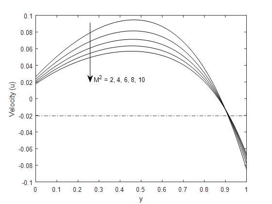
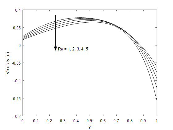
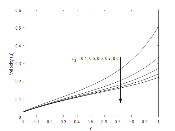
The velocity distribution within the channel results from the combined effects of magnetic resistance, wall suction or injection, and velocity slip at the boundaries. As the magnetic parameter \(M^2\) increases, velocity decreases due to the Lorentz force, which opposes motion. The coupling between the induced current and the external magnetic field creates an opposing electromagnetic drag that suppresses motion. Hence, a stronger magnetic intensity leads to greater resistance and a lower velocity magnitude, as illustrated in Figure 2. The variation of velocity with the Reynolds number, shown in Figure 3, emphasizes the effect of suction and injection at the porous boundary. When \(Re<0\) (injection), fluid enters the channel, increasing momentum transfer and raising the overall velocity. For \(Re>0\) (suction), fluid is pulled out through the wall, decreasing the available flow volume and lowering the velocity. This asymmetric response highlights the sensitivity of the flow to mass transfer at the boundaries, where injection boosts the profile, and suction reduces it. Wall slip introduces an additional layer of control depending on its position. At the lower wall, increasing the slip coefficient \(\beta_1\) reduces wall shear, thereby increasing the velocity near the boundary and enhancing the overall velocity profile. Conversely, higher slip at the upper wall \(\beta_2\) weakens the momentum exchange there, flattening the gradient and decreasing the near-wall velocity. The outcome is a decline in the overall velocity distribution, as presented in Figures 4 and 5, respectively.
The variations in skin friction, summarized in Tables 2–3, reflect the combined influence of inertial effects, magnetic forces, and slip conditions at the channel walls. At the lower wall, increasing the Reynolds number intensifies inertial forces, steepening the near-wall velocity gradient and consequently increasing the skin friction coefficient by approximately 8%. In contrast, at the upper wall, stronger inertia shifts momentum toward the channel core, leading to a flatter velocity profile near the wall and a substantial reduction in shear stress of about 41%. This contrasting behavior indicates that higher flow rates amplify wall loading at the driving boundary while alleviating shear at the opposing wall. The magnetic field exerts a consistent influence on both walls. As the magnetic parameter increases, the induced Lorentz force opposes fluid motion, resulting in steeper velocity gradients near the walls to counterbalance electromagnetic drag. Consequently, the skin friction coefficients at both walls exhibit an average increase of approximately 52%, demonstrating that stronger magnetic fields systematically enhance wall shear stresses. This outcome is particularly relevant in cooling and pumping applications, where magnetic control improves flow regulation but incurs higher frictional losses at the boundaries. Slip effects generally mitigate skin friction by weakening fluid–wall interactions. An increase in the slip parameter \(\beta_2\) leads to a reduction in skin friction at both walls, with an average decrease of about 10.1%, reflecting diminished viscous resistance due to enhanced slip. Similarly, increasing the lower-wall slip parameter \(\beta_1\) reduces the local shear stress at the lower wall by approximately 4.25%. This enhanced slip alters the velocity distribution across the channel, redistributing momentum toward the core and decreasing skin friction at the upper wall.
| \(\tau_{{0}}\) | \(\tau_{{1}}\) | ||||||||
|---|---|---|---|---|---|---|---|---|---|
| \({Re}{{/}{M}}^{{2}}\) | 2 | 4 | 6 | 10 | 2 | 4 | 6 | 10 | |
| 0.2 | -0.4278 | -0.1796 | -0.1038 | -0.0493 | -0.6444 | -0.4643 | -0.4616 | 10.4477 | |
| 0.4 | -0.4136 | -0.1764 | -0.1027 | -0.0486 | -0.6386 | -0.4717 | -0.4741 | 5.1987 | |
| 2 | -0.3010 | -0.1516 | -0.0941 | -0.0475 | -0.6167 | -0.5590 | -0.6223 | 1.0048 | |
| 4 | -0.2010 | -0.1253 | -0.0842 | -0.0450 | -0.6758 | -0.7898 | -1.1150 | 0.4866 |
| \(\tau_{{0}}\) | \(\tau_{{1}}\) | ||||||||
|---|---|---|---|---|---|---|---|---|---|
| \(\beta_{{2}}{\mathrm{/}}\beta_{{1}}\) | 0.01 | 0.05 | 0.1 | 0.2 | 0.01 | 0.05 | 0.1 | 0.2 | |
| 0.01 | -1.4394 | -1.4249 | -1.4080 | -1.3782 | -1.1034 | -1.1438 | -1.1905 | -1.2733 | |
| 0.05 | -1.4503 | -1.4367 | -1.4209 | -1.3930 | -1.2372 | -1.2372 | -1.2861 | -1.3723 | |
| 0.1 | -1.4668 | -1.4544 | -1.4401 | -1.4150 | -1.3332 | -1.3780 | -1.4295 | -1.5201 | |
| 0.2 | -1.5148 | -1.5056 | -1.4952 | -1.4772 | -1.7345 | -1.7839 | -1.8401 | -1.9372 |
The mass flux within the channel is governed by the combined effects of wall suction or injection, magnetic field intensity, and slip conditions at the boundaries. The physical role of suction and injection is straightforward: during injection, additional fluid enters the channel, increasing volumetric transport and thus raising the total mass flow rate. Conversely, suction removes fluid through the porous wall, thinning the flow region and lowering momentum transfer. These mechanisms hold practical importance; injection enhances transport processes such as mixing or biomedical flow delivery, whereas suction is often employed for boundary layer stabilization and improved heat transfer performance. Magnetic effects, however, oppose motion. As the magnetic parameter increases, the Lorentz force acts against the fluid movement, thereby reducing mass flux. The induced current interacts with the applied magnetic field to produce an opposing electromagnetic drag that suppresses the overall flow. This attenuation is observed under both suction and injection conditions, confirming the universally resistive nature of magnetic damping in MHD channel transport.
The mass flow rate decreases with increasing upper wall slip parameter because greater slip at the upper boundary reduces the velocity gradient and weakens the overall flow driving force. Conversely, an increase in the lower wall slip parameter enhances the fluid motion near the lower boundary, leading to a general increase in mass flow rate through the channel. Tables 4-5 summarize the mass flow rate.
| Mass flow rates \(\overline{(Q)}\) | ||||||||||
|---|---|---|---|---|---|---|---|---|---|---|
| \({Re}{/}{{M}}^{{2}}\) | 1 | 2 | 3 | 4 | \(\beta_2/\beta_1\) | 0.02 | 0.04 | 0.2 | 0.4 | |
| -2 | 0.1278 | 0.6013 | 0.5193 | 0.4293 | 0.01 | 0.1492 | 0.1647 | 0.1828 | 0.2147 | |
| -1 | 0.1324 | 0.6036 | 0.5200 | 0.4292 | 0.05 | 0.1301 | 0.1445 | 0.1611 | 0.1905 | |
| 1 | 0.1286 | 0.6002 | 0.5170 | 0.4264 | 0.1 | 0.0176 | 0.0260 | 0.0355 | 0.0520 | |
| 2 | 0.1199 | 0.5943 | 0.5131 | 0.4235 | 0.3 | -0.1382 | -0.1356 | -0.1326 | -0.1277 | |
| \({{Nu}}_{{0}}\) | \({{Nu}}_{{1}}\) | ||||||||
|---|---|---|---|---|---|---|---|---|---|
| \({Pe}{/}{Bi}\) | 1 | 3 | 6 | 8 | 1 | 3 | 6 | 8 | |
| 1 | 1.3057 | 1.1095 | 1.0640 | 1.0532 | 0.9184 | -1.1214 | -1.4822 | -1.5679 | |
| 3 | 0.2734 | 0.2935 | 0.2990 | 0.3004 | 0.6691 | 0.0250 | -0.1511 | -0.1962 | |
| 4 | 0.1348 | 0.1481 | 0.1519 | 0.1528 | 1.2206 | 0.8213 | 0.7088 | 0.6798 | |
| 5 | 0.0676 | 0.0745 | 0.0765 | 0.0770 | 1.9557 | 1.7116 | 1.6426 | 1.6247 | |
The variation of the Nusselt number at the channel walls highlights the combined influence of convective transport, magnetic effects, viscous dissipation, internal heat generation, and wall slip on the heat transfer characteristics. The results reveal a pronounced asymmetry between the lower and upper walls, driven by the imposed thermal and hydrodynamic boundary conditions.
As shown in Table 5, increasing the Peclet number and Biot number leads to a reduction in the Nusselt number at the lower wall. This trend indicates that stronger fluid advection and enhanced surface convection reduce the local temperature gradient at the heated wall, thereby lowering the wall heat transfer rate. At the upper wall, however, increasing \(Pe\) enhances the Nusselt number by approximately 121.94%, reflecting more efficient energy transport toward the channel interior by the moving fluid. In contrast, increasing \(Bi\) causes a substantial reduction of about 270.72% in the upper-wall Nusselt number, indicating that stronger heat exchange at the lower boundary restricts thermal penetration across the channel.
The effects of the Brinkman number \(Br\) and magnetic parameter \(M^2\), presented in Table 6, shows that the Nusselt number at the lower wall increases with both parameters. Higher \(Br\) intensifies viscous dissipation, raising fluid temperature and steepening the temperature gradient at the wall, which results in a 132.97% increase in heat transfer. Similarly, increasing magnetic strength enhances Joule heating near the wall, contributing a modest increase of about 0.95%. At the upper wall, the magnetic field slightly suppresses heat transfer, leading to a 2.70% decrease in the Nusselt number due to magnetic damping of fluid motion. However, increasing \(Br\) still enhances the upper-wall Nusselt number by 132.97%, confirming the dominant role of internal heat generation in strengthening thermal gradients. The influence of the heat source/sink parameter and the lower wall slip parameter \(\beta_1\) is depicted in Table 7. The presence of a heat source reduces the lower-wall Nusselt number by about 9.74%, while a heat sink produces a stronger reduction of 39.46%, reflecting diminished thermal gradients under volumetric cooling. At the upper wall, increasing \(\beta_1\) from 0.02 to 0.4 increases the Nusselt number by 53.58%, indicating that enhanced slip at the lower boundary redistributes momentum and promotes heat transport toward the upper wall. Moreover, the Nusselt number increases by 19.06% for the heat source and by 2.57% for the heat sink at the upper wall.
| \({{Nu}}_{{0}}\) | \({{Nu}}_{{1}}\) | ||||||||
|---|---|---|---|---|---|---|---|---|---|
| \({{Br}{/}{M}}^{{2}}\) | 4 | 6 | 8 | 10 | 4 | 6 | 8 | 10 | |
| 0.02 | 4.3766 | 4.3852 | 4.3980 | 4.4185 | 7.7425 | 7.7396 | 7.7349 | 7.7224 | |
| 0.2 | 4.7030 | 4.7899 | 4.9179 | 5.1228 | 7.7896 | 7.7403 | 7.6645 | 7.5392 | |
| 4 | 11.5942 | 13.3318 | 15.8925 | 19.9898 | 8.6800 | 7.6943 | 6.1785 | 3.6729 | |
| 6 | 15.2212 | 17.8276 | 21.6686 | 27.8145 | 9.1487 | 7.6701 | 5.3964 | 1.6381 | |
| \({{Nu}}_{{0}}\) | \({{Nu}}_{{1}}\) | ||||||||
|---|---|---|---|---|---|---|---|---|---|
| \({H}{/}\beta_{{1}}\) | 0.02 | 0.1 | 0.2 | 0.4 | 0.02 | 0.1 | 0.2 | 0.4 | |
| -2 | 1.2638 | 1.2466 | 1.2002 | 1.1407 | -2.5005 | -2.4428 | -2.0793 | -1.6107 | |
| -1 | 1.1034 | 1.0879 | 1.0468 | 0.9942 | -2.0230 | -1.9689 | -1.6184 | -1.1664 | |
| 1 | 0.8625 | 0.8496 | 0.8166 | 0.7744 | -1.2297 | -1.1813 | -0.8516 | -0.4264 | |
| 2 | 0.7916 | 0.7586 | 0.7287 | 0.6905 | -1.1988 | -0.8461 | -0.5249 | -0.1107 | |
In Table 8, variations in the heat source/sink parameter and the upper wall slip parameter \(\beta_2\) significantly affect the heat transfer behavior. At the lower wall, the Nusselt number rises by approximately 127.9% with increasing heat source strength, and also increases with \(\beta_2\), suggesting that slip at the upper wall indirectly enhances fluid motion and thermal gradients at the lower boundary. Conversely, at the upper wall, the Nusselt number decreases with increasing heat source strength and \(\beta_2\), but increases in the presence of a heat sink, consistent with reduced thermal gradients under heating and enhanced gradients under cooling. Overall, these findings demonstrate that wall slip, viscous dissipation, and internal heat generation play a dominant role in creating heat transfer asymmetry across the channel, while convective and magnetic effects govern whether local wall heat flux is enhanced or suppressed.
| \({{Nu}}_{{0}}\) | \({{Nu}}_{{1}}\) | ||||||||
|---|---|---|---|---|---|---|---|---|---|
| \({H}{/}\beta_{{2}}\) | 0.02 | 0.1 | 0.2 | 0.3 | 0.02 | 0.1 | 0.2 | 0.3 | |
| -2 | 1.0876 | 1.1054 | 1.2002 | 2.4797 | -1.1156 | -1.2730 | -2.0793 | -10.5409 | |
| -1 | 0.9481 | 0.9636 | 1.0468 | 2.1884 | -0.6885 | -0.8404 | -1.6184 | -9.7564 | |
| 1 | 0.7388 | 0.7510 | 0.8166 | 1.7494 | 0.0241 | -0.1191 | -0.8516 | -8.4722 | |
| 2 | 0.6590 | 0.6699 | 0.7287 | 1.5810 | 0.3284 | 0.1889 | -0.5249 | -7.9340 | |
The effect of the Brinkmann number on the temperature field, both excluding and including Joule dissipation, is shown in Figures 6 and 7, respectively. Both profiles demonstrate that temperature rises as Br increases. This occurs because a larger Br indicates stronger viscous dissipation (conversion of mechanical energy into heat); the additional internal heat generation raises the fluid temperature in both the heat-source and heat-sink configurations. Consequently, the overall thermal level increases, and the temperature gradients near the boundaries adjust accordingly. With Joule heating included, temperature is seen to rise for the heat source case while it declines for the heat sink case.
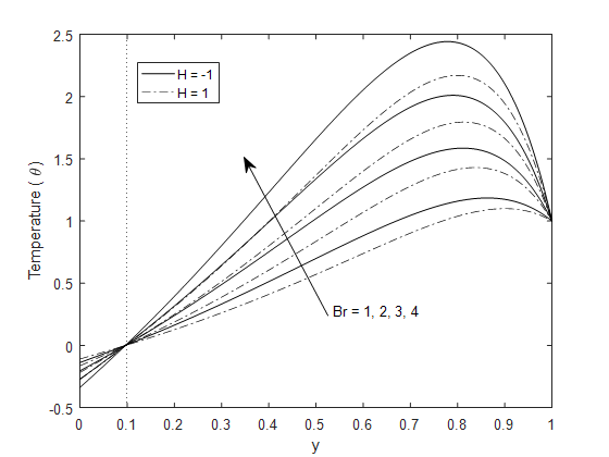
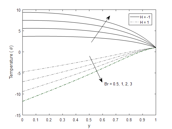
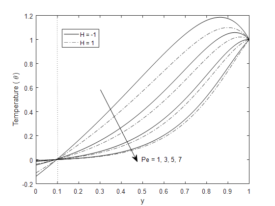
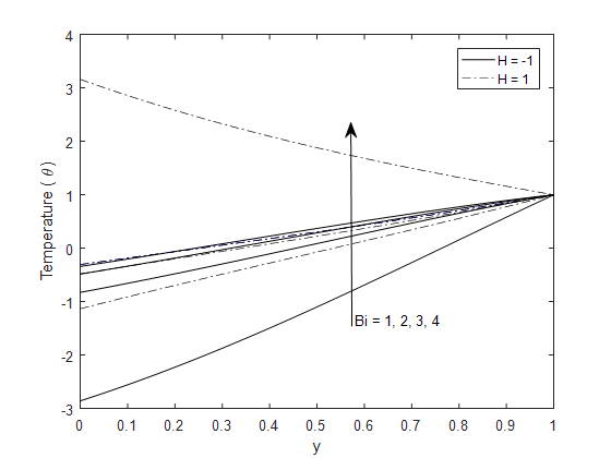
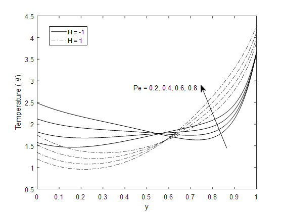
Figure 8 shows that as the Peclet number \(Pe\) increases, convective heat transport dominates over conduction, which reduces the temperature throughout the channel. A higher Peclet number strengthens advective heat transport relative to conduction, meaning the moving fluid carries thermal energy away from the heated region more efficiently. This enhanced convection thins the thermal boundary layer and reduces the overall temperature level within the flow field. An increase in the Biot number leads to a higher temperature within the channel. The Biot number measures the relative strength of convective heat transfer at the lower wall; larger values correspond to a stronger wall–fluid coupling. As \(Bi\) increases, the convective wall becomes more effective at exchanging heat with the surrounding medium, allowing more heat to enter the fluid domain from the lower wall. This additional heat input elevates the overall temperature, especially near the lower boundary. The relationship is depicted in Figure 9.
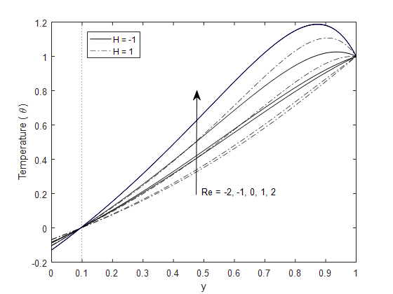
The relationship between the Reynolds number and the temperature of the fluid is shown in Figure 10. Injection through the porous wall diminishes the temperature field by introducing cooler fluid and enhancing convective heat removal, whereas suction suppresses this mixing, resulting in temperature build-up and a higher mean thermal level across the channel.
One consistent observation is the contrasting influence of heat source and heat sink terms. The addition of a volumetric heat source elevates the temperature across the channel, while a heat sink drives the fluid temperature to negative values relative to the reference state. This effect is especially prominent when Joule dissipation is excluded, as the absence of resistive heating allows the sink to dominate the energy balance. However, when Joule dissipation is included, its contribution compensates for the cooling effect of the sink, moderating the temperature decay and in many cases preventing it from falling below zero. High Biot numbers, while strengthening wall-fluid heat transfer, do not entirely counteract volumetric sinks, showing that wall convection has limits in controlling the bulk thermal state. Flow dynamics \((Re,\ Pe)\) add further complexity, redistributing heat in ways that reshape gradients, reversal points, and the overall symmetry of the temperature field. This comprehensive overview emphasises the importance of considering all thermal and hydrodynamic mechanisms together when analysing or designing systems with conducting fluids and slip boundaries.
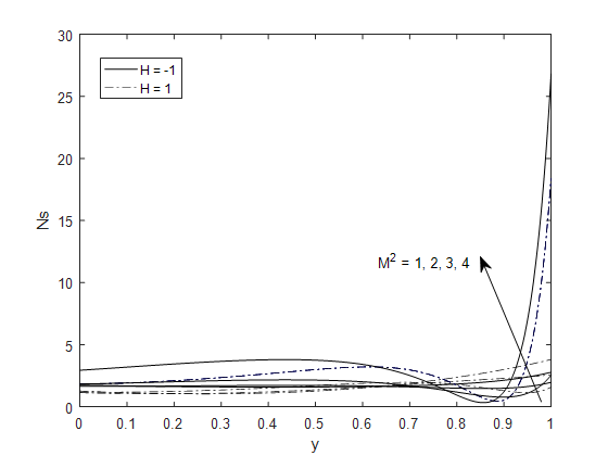
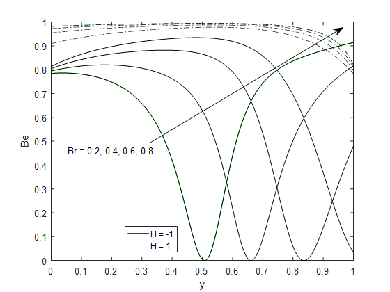
Figures 11–19 illustrate the relationship between key parameters on the entropy generation number, \(Ns\) for the flow configuration under heat-source and heat-sink conditions.
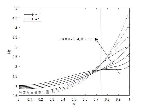
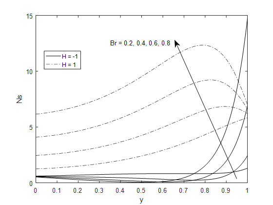
The entropy generation characteristics reflect the competing contributions of heat transfer irreversibility, viscous dissipation, and electromagnetic effects within the porous channel. In the absence of Joule heating, the local entropy generation number \(Ns\) decreases near the convective lower wall as the Brinkman number \(Br\) increases, owing to enhanced viscous heating that weakens local temperature gradients. Moving toward the isothermal upper wall, viscous dissipation becomes dominant, leading to a rise in entropy generation. When Joule heating is included, both viscous and Ohmic dissipation act simultaneously, amplifying temperature and velocity gradients across the entire channel. This interaction suppresses the earlier reversal in \(Ns\) profiles and produces a monotonic increase in entropy generation. Consequently, the integrated entropy generation rises sharply, exceeding the baseline value by 256.37%, confirming the dominant role of Joule heating in driving thermodynamic irreversibility in electrically conducting flows.
Increasing the magnetic field parameter further highlights this behavior. Near the lower wall, entropy generation initially decreases as Lorentz forces damp fluid motion and reduce velocity gradients. However, toward the upper wall, Joule heating intensifies, leading to a pronounced rise in \(Ns\). Under heat-source conditions, the entropy generation peak becomes significantly higher due to the additive effect of internal heat generation, producing a 153.64% increase in integrated entropy generation relative to the baseline state.
The Peclet number \(Pe\) redistributes entropy generation across the channel. Higher \(Pe\) reduces \(Ns\) near the lower wall through more effective convective cooling, while enhancing entropy generation near the upper wall as thermal energy transport strengthens temperature gradients. Similar profile shapes for heat-source and heat-sink cases indicate that \(Pe\) primarily shifts the location of irreversibility rather than altering its underlying mechanisms. Overall, increasing \(Pe\) from 1 to 4 results in a 37.25% rise in integrated entropy generation.
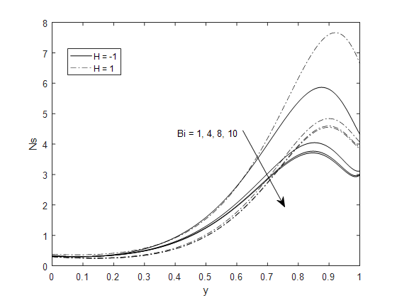
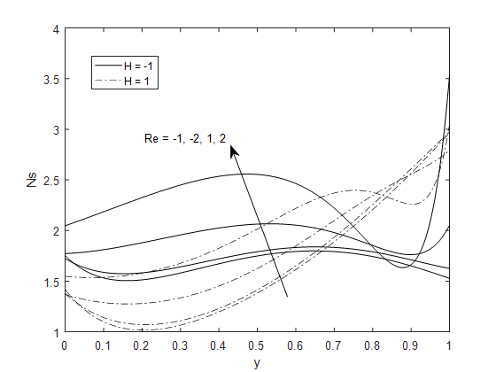
In contrast, increasing the Biot number consistently reduces entropy generation throughout the channel. Enhanced wall convection decreases temperature gradients at the fluid–wall interface, thereby lowering thermal irreversibility. This is evidenced by a 33.77% reduction in integrated entropy generation, highlighting the mitigating effect of convective boundary conditions. Mass transfer through the porous walls also plays a regulatory role. Fluid injection smooths velocity and temperature profiles, leading to a decrease in entropy generation, while suction increases gradients and boosts both viscous and thermal dissipation. Wall slip parameters significantly reshape entropy production. Increasing the lower-wall slip parameter \(\beta_1\) weakens near-wall shear, reducing local entropy generation and shifting the peak irreversibility toward the upper wall. This effect corresponds to a 45.83% decrease in integrated entropy generation relative to the baseline. Conversely, increasing the upper-wall slip parameter \(\beta_2\) produces a monotonic increase in \(Ns\), particularly under heat-sink conditions, although the corresponding change in integrated entropy generation remains modest (0.63%), indicating a secondary but non-negligible contribution.
Finally, variations in the group parameter reveal a mid-channel region where entropy generation profiles for heat-source and heat-sink cases overlap, suggesting a balance between viscous and thermal effects. Near the isothermal wall, entropy generation rises again as local gradients intensify, especially under heat-sink conditions, yielding an integrated entropy generation value of 46.10. Overall, the results demonstrate that entropy generation in the system is primarily governed by viscous dissipation and Joule heating, particularly in regions of strong velocity gradients and electromagnetic interaction. In contrast, wall convection, fluid injection, and lower-wall slip act as entropy suppression mechanisms while increasing \(Br\), magnetic intensity, \(Pe\), suction, and upper-wall slip enhance thermodynamic irreversibility.
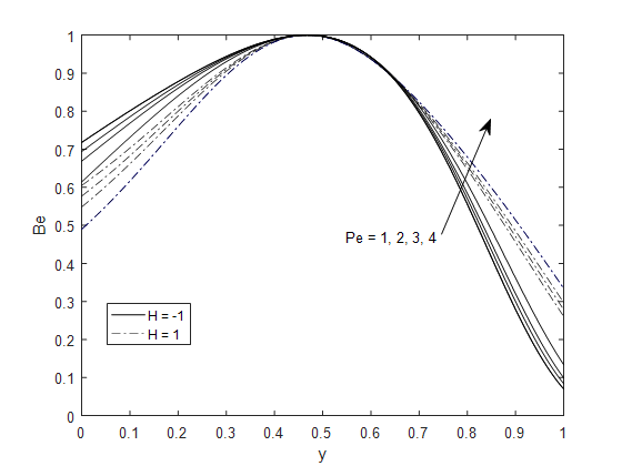
Figures 20–28 show the impact of governing parameters on the Bejan number \(Be\) for both heat-source and heat-sink conditions.
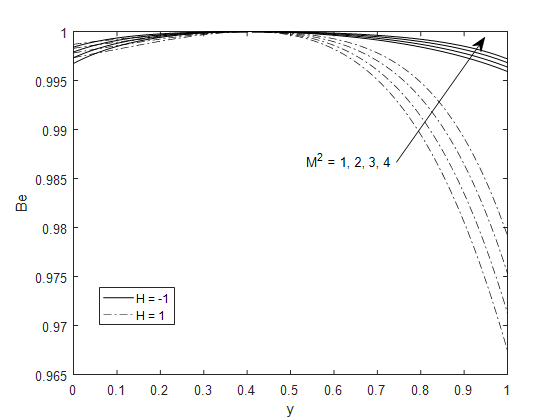
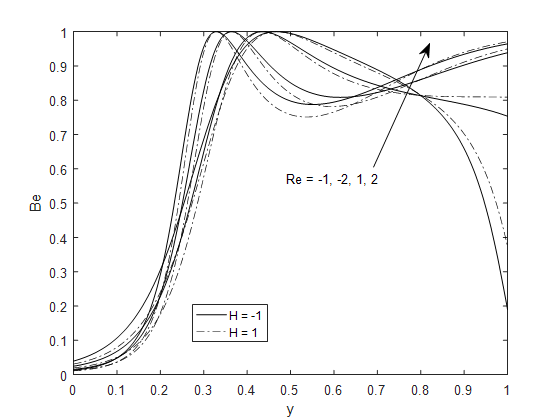
With increasing magnetic parameter \(M^2\), the Bejan number remains high across the channel, indicating dominance of thermal irreversibility. Only a slight dip occurs around \(y=0.4\), where weak viscous dissipation temporarily competes with heat-transfer effects. The persistently large \(Be\) values confirm that the magnetic field suppresses velocity gradients, leaving heat-transfer entropy as the main contributor to total irreversibility. For the Reynolds number \(Re\), Bejan number increases from low values near the lower wall to unity in the core region. Suction enhances \(Be\) by stabilizing the thermal layer and favoring heat-transfer irreversibility, while injection lowers \(Be\) due to stronger shear and viscous losses. This behaviour shows that suction improves thermodynamic performance, whereas injection promotes flow-driven irreversibility.
The Peclet number \(Pe\) exhibits a similar pattern to the Brinkman number as \(Be\) is observed to peak in the mid-channel, reflecting dominant thermal effects, but declines near the upper isothermal wall as stronger convection steepens velocity gradients and redistributes internal heat. The sharper fall in the heat-source case indicates that internal heat generation intensifies viscous dissipation in this region. An increase in the Biot number \(Bi\) reduces \(Be\) near the upper wall. Stronger wall convection effectively removes heat from the fluid, flattening temperature gradients and reducing the share of thermal entropy generation relative to viscous effects. For the velocity slip parameters \(\beta_1\) and \(\beta_2\), Bejan number decreases as slip increases. The partial slip condition weakens shear stresses and temperature gradients near the boundaries, thereby diminishing thermal irreversibility while enhancing the relative role of viscous entropy production. As the group parameter increases, \(Be\) briefly reverses near \(y\approx 0.45\) and then decreases steadily. This behavior marks a transition from thermally dominated to viscously dominated entropy generation as coupling between momentum and heat transfer strengthens.
This study examined the combined influence of velocity slip and convective boundary conditions on heat transfer and entropy generation in shear-driven flow of a viscous, incompressible, electrically conducting fluid with heat sources or sinks. Exact analytical solutions were derived, validated against established results, and used to evaluate velocity, temperature, and entropy fields. Graphical analyses highlighted the roles of magnetic, thermal, and hydrodynamic effects in governing system behaviour. The investigation demonstrates that thermal and entropy behaviours are strongly controlled by the interplay between slip effects, Biot number, and dissipative mechanisms, with distinct responses under heat-source and heat-sink conditions. Ohmic (Joule) heating was found to significantly impact temperature distributions and entropy generation. The key findings can be summarized as follows:
Brinkman effects: Increases temperature and entropy generation, with Joule dissipation amplifying these effects under heat-source conditions.
Magnetic parameter: Reduces velocity via the Lorentz force and enhances entropy generation, highlighting increased heat-transfer irreversibility.
Biot number: Higher \(Bi\) elevates near-wall temperatures and reduces overall entropy generation due to improved thermal regulation.
Reynolds number: Injection enhances velocity and reduces entropy generation by promoting cooling and smoother gradients, while suction compresses the flow, raising temperature and increasing entropy production. These effects remain consistent for both heating conditions.
Peclet number: Increasing \(Pe\) intensifies convective transport, which lowers fluid temperature but increases entropy generation. Larger \(Pe\) values strengthen advection, altering thermal distribution and shifting the balance between advection and diffusion.
Slip parameters: Velocity rises with increasing lower-wall slip parameter (\(\beta_1\)) but decreases with increasing upper-wall slip parameter (\(\beta_2\)). Both parameters enhance entropy generation by modifying shear and temperature gradients near the boundaries.
Group parameter: Higher group parameter values promote entropy generation under both heating conditions, reflecting stronger coupling between heat and momentum transport.
Joule heating: Joule dissipation plays a dominant role in controlling the thermal field and irreversibility, stabilizing temperature gradients and amplifying entropy generation, particularly under heat-source conditions.
Overall, the results underscore the critical role of slip and convective boundary conditions in determining flow, thermal management, and entropy production. The findings reveal subtle interactions between slip, magnetic effects, and boundary convection that shape velocity distributions, thermal layering, and energy transfer. These insights have the potential to provide valuable guidance for designing and optimizing microfluidic devices, porous cooling channels, and MHD-based thermal systems, enabling engineers to regulate localized heating, delay thermal reversals, and enhance energy efficiency in practical applications.
| \(Re\) | Reynolds number (dimensionless) |
| \(Br\) | Brinkmann number (dimensionless) |
| \(M^2\) | magnetic parameter (dimensionless) |
| \(Pe\) | Peclet number (dimensionless) |
| \(P\) | pressure term (dimensionless) |
| \(Nu\) | Nusselt number (dimensionless) |
| \(Q_0\) | dimensional heat source/sink parameter |
| \(Br{\Omega }^{-1}\) | Group parameter (dimensionless) |
| \(E_G\) | volumetric rate of entropy generation |
| \(Ns\) | entropy generation number (dimensionless) |
| \(N_h\) | entropy generation due to heat transfer (dimensionless) |
| \(N_f\) | entropy generation due to viscous dissipation (dimensionless) |
| \(H\) | heat source/sink parameter (dimensionless) |
| \(Bi\) | Biot number |
| \(\overline{Q}\) | mass flow rate |
| \(u'\) | dimensional velocity of the fluid |
| \(y'\) | coordinate perpendicular to the wall \([m]\) |
| \(h\) | channel width \([m]\) |
| \(v_0\) | suction/injection velocity |
| \(B_0\) | magnetic field intensity (Tesla) |
| \(\overrightarrow{F}\) | external force due to magnetic field, electric field, and buoyancy force |
| \(\frac{\overrightarrow{J}\bullet \overrightarrow{J}}{\sigma }\) | Joule or ohmic heating term |
| \(T\) | dimensional fluid temperature \([K]\) |
| \(T_0\) | temperature of the fluid at \(y'=0\) |
| \(q\) | heat flux \([Watt.m^{-2}]\) |
| \(\upsilon\) | kinematic viscosity \({[m}^2s^{-1}]\) |
| \(k\) | thermal conductivity \([W.{(mK)}^{-1}]\) |
| \(c_p\) | specific heat capacity at constant pressure \([J.{kg}^{-1}K^{-1}]\) |
| \(y\) | dimensionless vertical coordinate |
| \(u\) | dimensionless velocity of the fluid |
| \({\gamma }_1\) | slip coefficient at the lower wall (dimensional) |
| \({\gamma }_2\) | slip coefficient at the upper wall (dimensional) |
| \({\beta }_1\) | velocity slip at the lower wall (dimensionless) |
| \({\beta }_2\) | velocity slip at the upper wall (dimensionless) |
| \(\lambda\) | index for excluding and including Joule dissipation at \(\lambda =0\) and \(\lambda =1\ \)respectively |
| \(\theta\) | dimensionless fluid temperature |
| \(v\) | kinematic viscosity of the fluid [\(m^2s^{-1}]\) |
| \(\mu\) | fluid dynamic viscosity \([Ns.m^{-2}]\) |
| \(\rho\) | fluid density \([Kgm^{-3}]\) |
| \(\sigma\) | electrical conductivity \([Sm^{-1}]\) |
| \(\tau\) | skin friction |
| \({\Phi }\) | viscous dissipation term |
\[\begin{aligned} r=&{\left(\frac{{Re}^2}{4}+M^2\right)}^{\frac{1}{2}}.\\ X_1=&\frac{-\frac{P}{M^2}\left[r\beta_1e^{-\frac{Re}{2}}+Sinh(r)-\beta_2\left(\frac{Re}{2}Sinh(r)+rCosh(r)\right)\right]}{r\left(\beta_1-\beta_2\right)Cosh(r)+\ \left[\left(\frac{{Re}^2}{4}-r^2\right)\beta_1\beta_2-\frac{1}{2}Re\left(\beta_2+\beta_1\right)+1\right]Sinh(r)}.\\ Y_1=&\frac{P}{r\beta_1M^2}+\frac{X_1}{r}\left(\frac{1}{\beta_1}-\frac{1}{2}Re\right).\\ \eta =&\frac{1}{2}{\left({Pe}^2+4H\right)}^{\frac{1}{2}}. \end{aligned}\] \[\begin{aligned} C_1=&\frac{\left(\Psi_3+Bi\Psi_1\right)Sinh\left(\eta \right)-\eta \left(1+\Psi_2\right)e^{-\frac{Re}{2}}}{\left(\frac{Pe}{2}+Bi\right)Sinh\left(\eta \right)-\eta Cosh(\eta )},\\ C_2=&\frac{\left(1+\Psi_2\right)e^{-\frac{Pe}{2}}-C_1Cosh(\eta )}{Sinh\left(\eta \right)}. \end{aligned}\] \[\begin{aligned} Z_1=&\frac{{Re}^2}{4}{X_1}^2+{Y_1}^2r^2+rReX_1Y_1+\lambda M^2{X_1}^2,\\ Z_2=&7\frac{{Re}^2}{4}{Y_1}^2+{X_1}^2r^2+rReX_1Y_1+\lambda M^2{X_1}^2,\\ Z_3=&\frac{{Re}^2}{2}X_1Y_1+r(Re{X_1}^2+Re{Y_1}^2)+2{(r}^2X_1Y_1+\lambda M^2X_1Y_1),\\ Z_4=&2X_1P\lambda Z_5=2Y_1P\lambda . \end{aligned}\] \[\begin{aligned} X_2=&\frac{Z_1}{2[{Re}^2-RePe-H]} ,\\ X_3=&\frac{Z_1}{4[{\left(2r+Re\right)}^2-Pe\left(2r+Re\right)-H]} ,\\ X_4=&\frac{Z_1}{4[{\left(Re-2r\right)}^2-Pe\left(Re-2r\right)-H]},\\ X_5=&\frac{Z_2}{[{Re}^2-RePe-H]} ,\\ X_6=&\frac{Z_2}{2[{\left(2r+Re\right)}^2-Pe\left(2r+Re\right)-H]} ,\\ X_7=&\frac{Z_2}{2[{\left(Re-2r\right)}^2-Pe\left(Re-2r\right)-H]},\\ X_8=&\frac{Z_3}{4[{\left(2r+Re\right)}^2-Pe\left(2r+Re\right)-H]},\\ X_9=&\frac{Z_3}{4[{\left(Re-2r\right)}^2-Pe\left(Re-2r\right)-H]},\\ X_{10}=&\frac{Z_4}{2\left[{\left(r+\frac{1}{2}Re\right)}^2-Pe\left(r+\frac{1}{2}Re\right)-H\right]},\\ X_{11}=&\frac{Z_4}{2\left[{\left(\frac{1}{2}Re-r\right)}^2-Pe\left(\frac{1}{2}Re-r\right)-H\right]},\\ X_{12}=&\frac{Z_5}{2\left[{\left(r+\frac{1}{2}Re\right)}^2-Pe\left(r+\frac{1}{2}Re\right)-H\right]},\\ X_{13}=&\frac{Z_5}{2\left[{\left(\frac{1}{2}Re-r\right)}^2-Pe\left(\frac{1}{2}Re-r\right)-H\right]},\\ X_{14}=&\frac{\lambda P^2}{M^2H}. \end{aligned}\] \[\begin{aligned} Y_2=&X_2-X_5,\\ Y_3=&X_3+X_6+X_8,\\ Y_4=&X_4+X_7-X_9,\\ Y_5=&X_{10}+X_{12},\\ Y_6=&X_{11}-X_{13}. \end{aligned}\] \[\begin{aligned} \Psi_1=&Br(Y_2+Y_3+Y_5-X_{14}),\\ \Psi_3=&Br\left[Re\left(Y_2+Y_3\right)+2Y_4+\frac{ReY_5}{2}+rY_6\right],\\ \Psi_2=&Br\left[e^{Re}\left(Y_2+Y_3Cosh\left(2r\right)+Y_4Sinh(2r)\right)+e^{\frac{Re}{2}}\left(Y_5Cosh\left(r\right)+Y_6Sinh\left(r\right)-X_{14}\right)\right],\\ \Psi_4=&Br\left[Ree^{Re}\left(Y_2+Y_3Cosh\left(2r\right)+Y_4Sinh(2r)\right)+e^{Re}\left(2Y_3Sinh\left(2r\right)+2Y_4Cosh(2r)\right)\right.\\ &\left.+\frac{Re}{2}e^{Re}\left(Y_5Cosh\left(r\right)+Y_6Sinh(r)\right)+e^{\frac{Re}{2}}\left(rY_5Sinh\left(r\right)+rY_6Cosh\left(r\right)\right)\right]. \end{aligned}\]