
Fuel cells with proton-exchange membrane, called PEMFCs, are promising sources of energy for electricity conversion since they work at a relatively low temperature, have quick start-up characteristics, and generate DC energy with low local emissions. This makes PEMFCs appropriate for use in transportation, distributed generation, and DC microgrids. Nevertheless, the voltage output of such sources is normally low and dependent on the current of the load, supply of reactants, their pressure, temperature, and hydration level of the membrane [1–3]. Consequently, a power conditioning stage must be implemented between the fuel cell and the DC bus so that the voltage of the load would be stable while the electrochemical source is protected from the excessive current ripples and fast changes of current [1–3].
Interleaved boost converters are among the types of DC-DC converters that are appropriate for fuel cell systems since they split the input current into several phases and shift gate pulses of the converter phases. It leads to the decreased net input current ripples, reduced stress of semiconductor elements and inductors, enhanced thermal management, and higher power capability than a single phase converter with the same ratings [4–8]. In the case of a PEMFC source, lower ripples are particularly important since fast ripples of the source current can increase electrochemical stress of the source and deteriorate its performance and lifetime.
Control of an interleaved boost converter fed by a PEMFC is difficult since the source and the load may vary simultaneously. Load variations increase the converter current demands and lead to voltage drops due to the internal resistance and polarization losses of the fuel cell stack. Changes in environmental parameters, especially decrease in the operating pressure, affect the partial pressures of reactants and lead to the decreased reversible voltage of the cell according to the Nernst relationship. Previously, conventional PI or PID control, robust voltage control, sliding mode control, fractional order PID control, adaptive disturbance rejection, and optimization based regulators were analyzed for the PEMFC converter systems [9–15]. It was shown that disturbance rejection is powerful, but many advanced regulators imply complicated models and increased tuning and computation efforts.
The question arises whether a simple PI voltage regulator is able to ensure the maintenance of high DC bus voltage in the case when a PEMFC source experiences both load changes and pressure reduction. It is important since there are some practical systems, such as electric vehicles and standalone DC microgrids, which have varying load demands and operate in variable ambient conditions. The literature also shows that fuel cell voltage depends on pressure, temperature, and gas composition [16–18]. That is why the effect of pressure reduction must be taken into account together with the load transients and not considered separately as a source parameter.
The aim of this research is to analyze a model of a 12 kW PEMFC DC system with a PI-controlled two-phase interleaved boost converter in three cases: load transients at constant pressure, pressure transients at constant load, and simultaneous load and pressure transients. It is necessary to find out whether the closed loop converter ensures the maintenance of DC bus voltage at 400 V when the PEMFC voltage varies due to the electrochemical and load factors.
A control-oriented PEMFC model is needed to describe how the source voltage changes with current demand and environmental conditions. The terminal voltage of a PEMFC stack can be written as the reversible thermodynamic voltage minus activation, ohmic, and concentration losses. For a stack containing \(N_{\mathrm{cell}}\) cells connected in series, the stack voltage is expressed as
where \(E_{\mathrm{Nernst}}\) is the reversible cell voltage, \(V_{\mathrm{act}}\) is the activation overpotential associated with electrode reaction kinetics, \(V_{\Omega}\) is the ohmic voltage drop caused by ionic and electronic resistances, and \(V_{\mathrm{conc}}\) is the concentration overpotential associated with mass-transport limitations [2,3].
For system-level converter design, the same voltage behaviour can be represented in compact form as
where \(V_{\mathrm{FC}}\) is the fuel-cell terminal voltage, \(E\) is the open-circuit electrochemical voltage, \(I\) is the stack current, \(R_{\mathrm{int}}\) is the equivalent internal resistance, and \(V_{\mathrm{loss}}\) collects the activation and concentration losses. Eq. (2) explains the main voltage trends observed in the dynamic results: an increase in load current increases \(I R_{\mathrm{int}}\), while a reduction in reactant pressure lowers \(E\) and increases mass-transport limitations.
The pressure dependence of the reversible voltage is described by the Nernst equation,
where \(E^{0}\) is the standard reversible potential, \(R\) is the universal gas constant, \(T\) is the absolute temperature, \(F\) is Faraday’s constant, and \(P_{H_2}\), \(P_{O_2}\), and \(P_{H_2O}\) are the partial pressures of hydrogen, oxygen, and water vapour, respectively. A pressure reduction lowers the available oxygen partial pressure and therefore reduces the reversible voltage. This mechanism is consistent with PEMFC pressure-sensitivity studies that relate pressure, temperature, and water content to electrochemical performance [16–18].
A two-phase interleaved boost converter is used to connect the PEMFC source to the regulated DC bus. Each phase contains an inductor, a controlled switch, and a diode path to the output capacitor and load. The two switches operate with the same duty ratio and a phase displacement of \(180^{\circ}\), so the input current is shared between the two inductors and the ripple components partially cancel at the fuel-cell terminals [4,19,20].
Under continuous conduction mode and ideal steady-state assumptions, the boost-converter voltage conversion relation is
where \(V_o\) is the output DC bus voltage, \(V_{\mathrm{in}}\) is the PEMFC input voltage to the converter, and \(D\) is the duty ratio. The nominal duty ratio corresponding to a 90 V input and a 400 V bus is approximately \(D=0.775\).
The steady-state power balance can be written as
where \(P_o\) is the output power, \(I_o\) is the output current, \(I_{\mathrm{in}}\) is the source current, and \(\eta\) is the converter efficiency. For an \(N\)-phase interleaved converter, the average current in each phase is
For the two-phase case, Eq. (6) indicates that each inductor carries approximately half of the input current under balanced operation. This current sharing reduces conduction stress and supports stable voltage regulation under transient loading.
The investigated PEMFC power system is shown in Figure 1. The source is composed of two PEMFC stacks connected in series. Each stack is rated at 6 kW, giving a total nominal power of 12 kW. The series connection raises the input voltage available to the boost converter, while the two-phase interleaved converter raises and regulates the output at a 400 V DC bus. A single outer voltage loop measures the DC bus voltage, compares it with the reference voltage, and updates the converter duty command through a PI controller.
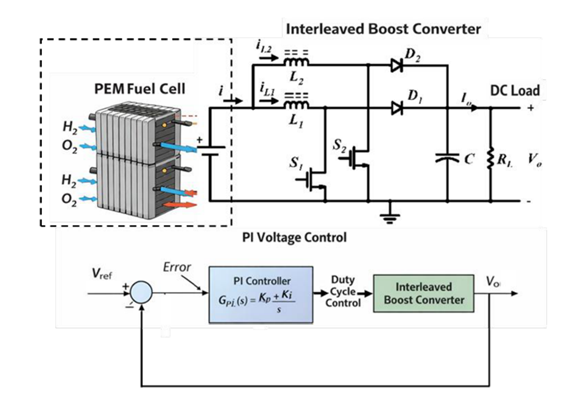
The PEMFC and DC bus specifications used for the converter design are listed in Table 1. These values define the nominal electrical operating point for the control and converter sizing calculations.
| Parameter | Symbol | Value | Unit |
|---|---|---|---|
| Number of PEMFC stacks | – | 2 | – |
| Rated power per stack | \(P_{\mathrm{stack}}\) | 6 | kW |
| Total rated power | \(P_{\mathrm{in}}\) | 12 | kW |
| Nominal stack voltage | \(V_{\mathrm{stack}}\) | 45 | V |
| Total nominal input voltage | \(V_{\mathrm{in}}\) | 90 | V |
| Input current at 12 kW | \(I_{\mathrm{in}}\) | 133 | A |
| DC bus reference voltage | \(V_o\) | 400 | V |
| Output current at 12 kW | \(I_o\) | 30 | A |
The main converter parameters are summarized in Table 2. The design uses two interleaved phases, a \(180^{\circ}\) phase shift, and a switching frequency of 5 kHz. The output-voltage ripple entry is reported as 1% because the selected 4 V ripple allowance corresponds to 1% of the 400 V bus.
| Parameter | Symbol | Value | Unit |
|---|---|---|---|
| Number of phases | \(N\) | 2 | – |
| Phase shift | \(\phi\) | 180 | degree |
| Nominal duty ratio | \(D\) | 0.775 | – |
| Average inductor current per phase | \(I_{L,\mathrm{avg}}\) | 66.7 | A |
| Current ripple ratio | \(r_L\) | 20 | % |
| Inductor ripple current per phase | \(\Delta I_L\) | 13.3 | A |
| Switching frequency | \(f_s\) | 5 | kHz |
| Inductance per phase | \(L\) | 1 | mH |
| Voltage ripple ratio | \(r_C\) | 1 | % |
| Allowed voltage ripple | \(\Delta V_o\) | 4 | V |
| Output capacitance | \(C\) | 680 | \(\mu\)F |
The control objective is to maintain the DC bus at \(V_{\mathrm{ref}}=400\) V despite changes in load power and source voltage. The measured output voltage \(V_o\) is subtracted from the reference voltage to form the error signal. This error is processed by a PI compensator,
where \(K_p\) improves transient response and \(K_i\) removes steady-state error. The controller output is converted to a duty-cycle command and applied to the two PWM channels with a \(180^{\circ}\) phase displacement. The interleaving reduces the effective input ripple, while the PI loop corrects bus-voltage deviations caused by load steps or fuel-cell voltage changes. This combination allows the converter to regulate the load-side bus without requiring a high-order nonlinear controller [1,9,10].
Dynamic performance is investigated in three operation cases. In the first case, DC load-power step changes occur with constant 1.0 bar atmospheric pressure. In the second case, pressure reduction from 1.0 bar to 0.3 bar is applied under the condition of constant load. In the last case, the pressure reduction is combined with load-power steps. The fuel-cell voltage will be used to evaluate the source-side stresses. The DC bus voltage is applied to analyze the load-side dynamic performance.
The first experiment evaluates the ability of the system to regulate the bus voltage at the reference level when there are step changes in load power at constant pressure. Figure 2 displays the load-power step inputs and the corresponding fuel-cell voltage outputs.
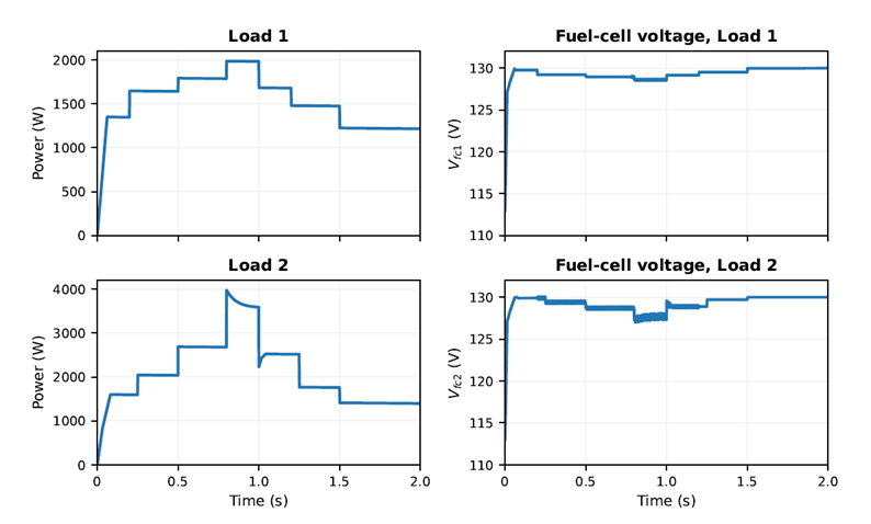
The fuel-cell voltage decreases with an increase of load because a higher load intensity causes additional voltage drops related to activation and ohmic losses in Eq. (2). With the lower-power load 1 input, the fuel-cell voltage remains almost stable after the start-up transient period because it means that the converter requests current within the capability of fuel-cell source without any source side stresses. With the higher-power load 2 input, the fuel-cell voltage demonstrates more distinct dips and a greater high-frequency component during the high-demand interval because there are more activation and ohmic losses in the fuel cell stack. The important point is that the fuel-cell voltage doesn’t collapse, it means that the closed-loop controlled converter doesn’t request unattainable currents under load steps.
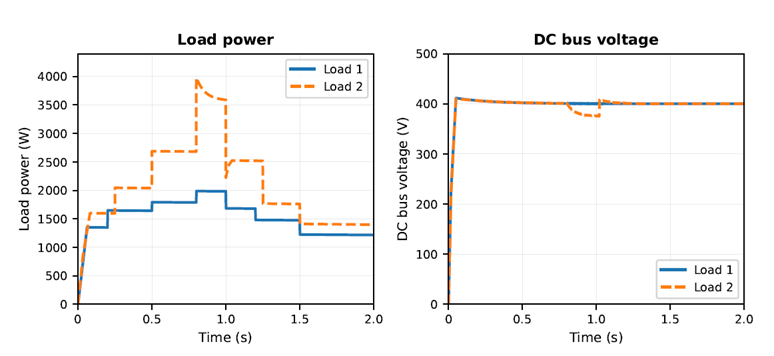
The bus-voltage response in Figure 3 demonstrates an efficient performance of the load-side regulation. After the start-up transient, the DC bus voltage maintains a close level to the 400 V reference even with load-power step changes. With the higher-power load 2 input, there is a little deviation in the bus voltage, but it is a temporary one because the converter increases the duty ratio to provide load demand. Therefore, the bus voltage returns to the regulated value without any oscillations, which proves that the PI controller and the interleaved power stage give sufficient dynamic damping properties to maintain the regulation.
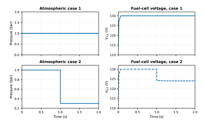
The second experiment isolates the effect of source-side pressure reduction. The pressure remains at 1.0 bar in the first atmospheric input case and is reduced from 1.0 bar to 0.3 bar at \(t=1\) s in the second atmospheric input case. This experiment is interesting because the pressure affects directly the oxygen partial pressure and therefore the reversible voltage in Eq. (3).
Figure 4 illustrates that the DC bus voltage remains tightly regulated near 400 V level with the pressure reduction. Under the low-pressure case, the bus voltage experiences only slight transient effects because of the PI controller, which increases the converter duty ratio to compensate the decrease in the source voltage. This fact is important because the bus voltage is the voltage which is supplied to the load. This result means that the load is effectively decoupled from the electrochemical pressure disturbance over the simulated interval.
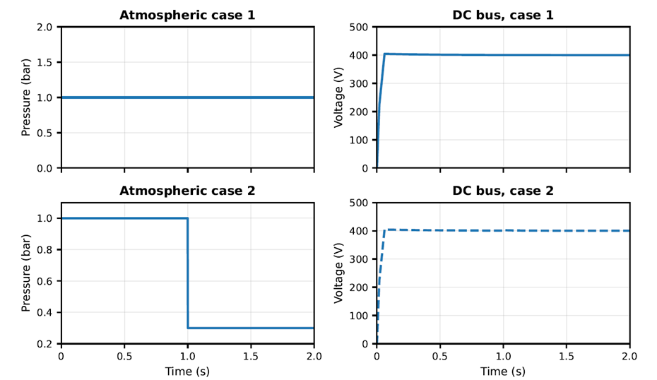
The source-side response in Figure 5 illustrates the physical impact of the pressure reduction. At constant pressure equal to 1.0 bar, the fuel-cell voltage remains steady after the start-up transient. When pressure reduces to 0.3 bar, the fuel-cell voltage settles at a lower voltage level, it is explained by Eq. (3). This equation states that the fuel-cell voltage reduces with the decrease in the oxygen partial pressure. The simultaneous analysis of Figures 4 and 5 shows that the converter keeps the bus voltage regulation even under the pressure disturbance.
The third experiment applies the most extreme operating conditions considered in this paper. Pressure reduction from 1.0 bar to 0.3 bar at \(t=1\) s and the load-power variation are applied simultaneously. This experiment evaluates the ability of the system to regulate the bus voltage when the source capability and the load demand vary together.
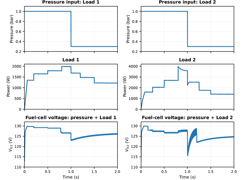
The combined response in Figure 6 shows that the fuel-cell voltage depends on the load current and reactant pressure. Before the pressure reduction step, load increases cause the moderate fuel-cell voltage reduction caused by the current-dependent voltage drop in Eq. (2). After the pressure drops, the fuel-cell voltage reduces more sharply because there are the open-circuit voltage reduction and the persistent current demand. Load 1 causes higher output voltage level than load 2 after the pressure reduction because of a smaller current stress on the fuel cell stack.
The DC bus response in Figure 7 is the strongest evidence of closed-loop robustness. Even when the fuel-cell voltage drops due to reduced pressure and the load profile changes at the same time, the bus voltage remains close to the 400 V reference. The larger Load 2 case produces a slightly more pronounced bus-voltage deviation than Load 1 because the converter must handle both a lower source voltage and a higher current demand. The deviation is corrected without growing oscillations, which indicates that the PI controller has sufficient damping for the tested disturbance magnitude. Therefore, the interleaved topology and voltage loop together provide the required energy-transfer adjustment between the PEMFC source and the regulated DC load.
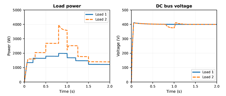
It is apparent from the presented plots that the results are indicative of a clear distinction between the source-side and load-side effects on the system behavior. The voltage of the PEMFC is permitted to reach a new operational level upon changing pressure, while the output voltage of the converter remains fixed due to the controlled operation of the DC bus. In practical terms, this is crucial since it is impossible to assume that the fuel cell acts as an ideal voltage source; thus, a properly stable converter must account for any variations in its voltage level and provide regulated bus voltage. It is clear from the provided responses that the chosen PI-controlled interleaved boost converter is capable of doing that for the particular test cases.
The problem addressed in this study was related to the ability of a PI-controlled two-phase interleaved boost converter to keep a 400 V DC bus regulated for the PEMFC power system during load variation, atmospheric-pressure reduction, and both source-side and load-side disturbances. The results have shown that the chosen solution allows solving this task positively. Upon load variation at the fixed value of pressure, the fuel-cell voltage decreased as expected under the load current; however, the DC bus was successfully regulated after the transients. Under the pressure reduction from 1.0 bar to 0.3 bar, the voltage of the PEMFC decreased due to the lower pressure of the reactants; however, the bus voltage was kept close to the 400 V set point. Simultaneous load and pressure variation led to the greatest decrease in the fuel-cell voltage, especially in the case of the high-power load profile; however, the converter managed to avoid bus-voltage collapse and restore the regulated level.
The main result of the work lies in the demonstration of the possibility of practical disturbance rejection in a PEMFC-powered DC system based on a two-phase interleaved boost converter with a well-designed PI voltage loop without the need for a complex controller. In this way, the interleaving topology provides the reduction of the current ripples and distribution of the currents, while the PI controller compensates for the voltage degradation and power variations by controlling the duty cycle of the switches.
The limitations of the study are associated with the simulation approach and the examination of the operation of the model under specific operating conditions. The extended work under the conditions of low pressure may lead to increased reactant demand and thermal and mechanical stress, and the further PEMFC degradation, which requires experimental verification of the PEMFC models and hardware testing.
Acknowledgments: The author acknowledges Dr. Akuro Big-Alabo for encouragement, constructive comments, and proofreading support. The author also acknowledges the Alexander von Humboldt Foundation for supporting the research fellowship of which this work forms a part.
Data Availability: All data used to support the findings of this study are presented in the manuscript.
Conflicts of Interest: The author declares no conflict of interest.